UPDATE FROM GIANDEL (PS3000-KAR only):
----------------------------------------------------------------------
Firstly,
This situation is normal, it is only induced voltage, and no practical significance. Our inverter generally only measures the voltage from the hot relative to the neutral relative.
The internal wiring of our inverter is correct, please don't worry.
We are certain that the quality of our products have no problem. Our factory has undergone strict manufacturing and testing, and finally produces good products.
We have been engaged in the inverters industry for 20 years, we clearly know that the quality of the inverters and customer service are very important.
We (Giandel) will always stand behind our products.
-----------------------------------------------------------------------
So as a mechanical engineer, who started in electrical engineering, I am actually trying to figure this out and I am not sure I totally understand this yet. I think what concerns me is when I powered half my panel (one side) from the inverter terminal blocks with no ground neutral bond I had the following:
Powered side: 95 Volts
'Unpowered' Side: 25 Volts
The total is obviously 120 Volts. The ONLY way I would be getting 25 volts through the 'unpowered' side of my panel is through the ground to neutral connection. I was originally ok with no N-G bond as the inverter has overload and short circuit protection. But based on my testing, the Neutral wire is clearly acting as the hot and the ground may be acting as a neutral with no load (potential differential only).
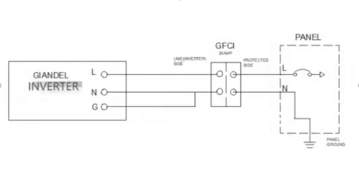
So at this point I either complete the Giandel Recommendation from the image (attached) or ditch it and go to a UL1781 inverter - which I should just do anyway - this has been a good learning experience at least. The UL458 / ETL listed unless is not suitable for my needs at this point even though I am off grid.
@Will Prowse this discussion may make for a good video regarding differences between UL1781/UL458 and how they are designed. It also may be good to include some internal images and wiring of the lower end high frequency inverters to show what is actually happening. Thanks or all you do - and keep it up!


 ,,, especially if small font. Maybe these manufacturers should colour code their “stuff”.
 ;
;