Does anyone know if any 24v inverter or inverter charger is for sale that allows you to adjust the low battery voltage cut off point? All the ones I look at seem to set it so low from factory as to be at battery full discharge. I have this ability in my off grid AIO and it is a feature I think is important.


You are using an out of date browser. It may not display this or other websites correctly.
You should upgrade or use an alternative browser.
You should upgrade or use an alternative browser.
Inverter or Inv/charger with adjustable low voltage cut out?
- Thread starter Mattb4
- Start date
BentleyJ
Solar Wizard
Try the Schneider SW4024, I believe it has a user settable LBCO.
Thanks. I looked at the Schneider SW and it does look nice. Too bad it is over $1600. Might be worth it though. I did notice that it mentions an external control panel (that was not presently available on Amazon). Maybe if I win the lottery I will buy it and the corresponding Schneider 60a SCC. ")
John Frum
Tell me your problems
- Joined
- Nov 30, 2019
- Messages
- 15,233
The victron phoenix has configurable low voltage disconnect.Does anyone know if any 24v inverter or inverter charger is for sale that allows you to adjust the low battery voltage cut off point? All the ones I look at seem to set it so low from factory as to be at battery full discharge. I have this ability in my off grid AIO and it is a feature I think is important.
Requires a bluetooth dongle though.
MaximusAnonus
New Member
Not only it needs BT it also needs GPS location and acces to your clipboard lmao. Victron is such a joke.
Looking up Victron ap on the play store it does have a comment about location requirement dictated by Android and Bluetooth. I also see that you can also use Victron software on various PC OS's and USB cables to corresponding Victron port. It would be much more handy if Victron had all settings available at the inverter.
MaximusAnonus
New Member
Well sure you can use VE.Config (that's what I use) but it seems it's being slowly phased out in favor of the more "modern" apps. Honestly as a LONG time Linux user and general FOSS advocate I have no love for Victron. Their whole support (not the paid one, the paid one is superb) is appalling. The online documentation is a joke too.
Something as critical as power should be completely FOSS and as secure as it gets.
Something as critical as power should be completely FOSS and as secure as it gets.
MaximusAnonus
New Member
By the way what inverters/chargers are you looking at that can't set the cut off points? Sometimes they don't state it in the datasheet that you can set the cutoff but once you read the manual you will find out it can be set (but usually only with single digit precision). But a good BMS as a falesafe is a must.
I try and read the manual for all inverters I get interested in. I assume if they do not have a section in the manual on changing parameters that it is not available for the typical user. I am sure if you knew what you were doing and had access to the logic controllers on these things you could accomplish a lot more. After all the factory has to set these to begin with.By the way what inverters/chargers are you looking at that can't set the cut off points? Sometimes they don't state it in the datasheet that you can set the cutoff but once you read the manual you will find out it can be set (but usually only with single digit precision). But a good BMS as a falesafe is a must.
MaximusAnonus
New Member
TBH if it doesn't even have a section in the manual about setting stuff then it's not worth buying.
Or DIY something external. An Arduino and a switch would be enough I bet but not as elegant.
Or DIY something external. An Arduino and a switch would be enough I bet but not as elegant.
BlueMarblePA
Solar Enthusiast
I have a Cotek inverter 24v-1500 watt which has a remote control port. Could I use the port to turn the inverter on and off by connecting it to an external low voltage monitor?
John Frum
Tell me your problems
- Joined
- Nov 30, 2019
- Messages
- 15,233
Maybe.I have a Cotek inverter 24v-1500 watt which has a remote control port. Could I use the port to turn the inverter on and off by connecting it to an external low voltage monitor?
Post a product link and I will take a look.
BlueMarblePA
Solar Enthusiast
Cool
If you click on the specs and downloads, you can get the manual and spec sheet

 invertersrus.com
There is also an associated remote
 invertersrus.com
I assume that there should be a way to wire this in such a way as to shut off at a higher voltage than the built in inverter low voltage shut off which is too high for my Battleborn LiFePO4 batteries.
Thanks in advance.
If you click on the specs and downloads, you can get the manual and spec sheet
COTEK SK1500-124 1500 Watt 24V Pure Sine | Inverters R Us
The Cotek SK1500-124 Industrial Grade 1500 Watt 24 Volt Pure Sine Wave Inverter has free ground shipping everyday. Call us today!
invertersrus.com
There is also an associated remote
COTEK CR-8 Remote Control for SK, ST & SP Series Inverters
COTEK CR-8 Remote Control works with the SK, ST & SP Series power inverters, allowing you to turn the inverter on from afar with a simply push of a button.
invertersrus.com
I assume that there should be a way to wire this in such a way as to shut off at a higher voltage than the built in inverter low voltage shut off which is too high for my Battleborn LiFePO4 batteries.
Thanks in advance.
John Frum
Tell me your problems
- Joined
- Nov 30, 2019
- Messages
- 15,233
Cool
If you click on the specs and downloads, you can get the manual and spec sheet
COTEK SK1500-124 1500 Watt 24V Pure Sine | Inverters R Us
The Cotek SK1500-124 Industrial Grade 1500 Watt 24 Volt Pure Sine Wave Inverter has free ground shipping everyday. Call us today!
There is also an associated remote
COTEK CR-8 Remote Control for SK, ST & SP Series Inverters
COTEK CR-8 Remote Control works with the SK, ST & SP Series power inverters, allowing you to turn the inverter on from afar with a simply push of a button.
I assume that there should be a way to wire this in such a way as to shut off at a higher voltage than the built in inverter low voltage shut off which is too high for my Battleborn LiFePO4 batteries.
Thanks in advance.
I can't tell from the manual.
Often times you just need to short 2 pins to turn the unit on.
BlueMarblePA
Solar Enthusiast
Perhaps this CR-8 manual can help. it does show the RJ-11 wiring diagramI can't tell from the manual.
Often times you just need to short 2 pins to turn the unit on.
This is not the same inverter as it is the CP version, but in the manual it does describe the RJ-11 wiring on page 31
3-2-1. Remote Port (RJ-11) The SP Series Inverter can be compatible with CR-8, and CR-16 remote control via RS-232 Communication. Before using the remote control, make sure the main switch on inverter must be at “ REMOTE” position.
Pin Number Signal Description ①
1 Reserved --
2 GND The same polarity as the battery negative side
3 RXD RS232 RXD
4 TXD RS232 TXD
5 RMT Remote controller panel (positive)
6 VCC Internal power for remote controller
Table 28. SP Series Remote Port : RJ-11 3-2-2. Remote Control Green Terminal Remote control green terminal ② may be connected to a Form C relay for “FAULT” indication. When “FAULT” occurs, the relay switches.
Figure 13. Remote control terminal Item Description Item Description
1 Dry contact (Normal Open)
4 Enable+ (ENB)
2 Common
5 Enable- (ENB)
3 Dry contact (Normal Closed)
6 Ground Table
29. Dry contact terminal definition Note! Pin-6 is the same polarity with battery negative electrode.
32 Note! Fault conditions include Input under / over voltage, output short circuit / over load, over / under temperature.
Caution! Please follow the following steps for the installation Before installing the inverter, make sure the main switch is at “OFF” position. Before using the remote function, make sure the main switch pressed toward “REMOTE”
Use 20 ~ 24 #AWG wire to connect the remote control terminals Figure 14. Wiring for control
BlueMarblePA
Solar Enthusiast
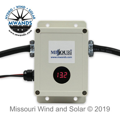
I found another solution. I could add this disconnect. It works on the AC side rather than the DC side. It doesn't shut off the inverter but rather shuts off the AC load. In my case this would work because I want to run a pool vacuum cleaner and pump but don't want to drain the battery
 windandsolar.com
Battery Saver Smart AC Shutoff Module
Save more when you DIY. Call our sales techs for a free quote on how to install your own wind and solar power.
windandsolar.com
John Frum
Tell me your problems
- Joined
- Nov 30, 2019
- Messages
- 15,233
I forgot about that solution.I found another solution. I could add this disconnect. It works on the AC side rather than the DC side. It doesn't shut off the inverter but rather shuts off the AC load. In my case this would work because I want to run a pool vacuum cleaner and pump but don't want to drain the battery
Battery Saver Smart AC Shutoff Module
Save more when you DIY. Call our sales techs for a free quote on how to install your own wind and solar power.
Looks good to me.
Nice easy solution and not much more money than a battery protect and a solid state relay.
Similar threads
- Replies
- 17
- Views
- 461
- Replies
- 0
- Views
- 113
- Replies
- 11
- Views
- 377
- Replies
- 5
- Views
- 551