diy solar

diy solar

JK-BMS B2A8S20P worked for a moment and not anymore

LaFabrik

New Member
Joined
Mar 11, 2021
Messages
43
Location
France
I want to share something with you guy, maybe you can help me ?
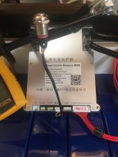
i bought 2 JK-BMS (B2A8S20P)
at first both worked perfectly, and with no reason one stop working ! :(

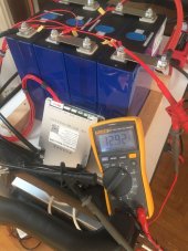
I have 4cells (in serie) each cell is 3,335V
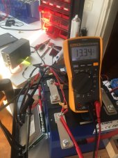
the voltage between this 4S string is 13,34V
voltage between + 4cells and B- (BMS) is 12,92V !!!
i can't turn on the BMS neither with the switch, neither with the old fashion way (9V between B- and P-

Do you have anu suggestion please ?
Thanks a lot for your help guys
 

Attachments

  • 297871222_428764039312543_4096880066238298316_n.jpg
    297871222_428764039312543_4096880066238298316_n.jpg
    78.2 KB · Views: 47
  • 298324710_776003546774907_4083428125823081833_n.jpg
    298324710_776003546774907_4083428125823081833_n.jpg
    92.3 KB · Views: 45
  • 298310239_1029159131106898_6526513971658317037_n.jpg
    298310239_1029159131106898_6526513971658317037_n.jpg
    92.3 KB · Views: 44
I looked at the photo; B-, B1...B4, B+ wires connected to the right cell terminals.
I hope there is no break (open circuit) on the wires.

old fashion way (9V between B- and P-
disconnect push button.
Make sure that B- is higher than P- by +5V (use a low current power supply).
1660327336599.png
If this still does not turn it on, and all connections are good, could be dead.
 
I hope there is no break (open circuit) on the wires.
i checked all of that with voltmeter, here all is ok


Make sure that B- is higher than P- by +5V (use a low current power supply).

-> yes, i disconnected the push button and i tried with my power sypply +5V even +9V (with 2A and 5A), still nothing
 
I own the nearly identical B1A8S20P, being a very early tester of the unit. It may have been a bad mistake to try "the old fashioned way" described by @burgerking", with a full 5v applied on the two sides of the BMS. But your photo #1 does NOT show the temp sensor header port connected. AFAIK, the JK will refuse to active when the temp sensor port has not been connected.

After you plug that in, I recommend the following procedure:

1) disconnect the balance wire header from the BMS. This will remove power from the BMS, which uses the top-most pin of the header to receive "12v" power for running its own circuitry.

2) Using a DVM volt meter with small probe ends, test the voltage of each port (on the plugin) against its neighbor. You should a voltage increase of 3.35v from 0-1, 1-2, 2-3, and 3-4. Also check that the final port (#9) has voltage of about 13.34v in comparison to grounding voltage on port #0. Verify that NONE of ports 5-8 show any voltage at all.

3) Verify that the port for the dual temp sensors is plugged in first. If the heater port plug is connected and mis-wired, that could introduce a problem. So I would remove it before plugging the the sense wire header back in.

4) Verify that the B- leads to the battery (from BMS) and the P- leads (from BMS to system grounding bus) are tight. If you are unsure of the system grounding connection or its voltage, you can disconnect the P- leads from the grounding bus, leaving the ends "free" to connect a charger directly.

5) Plug the sense wire header back in.

6) Connect a DC battery charger, @ about 14.2V, between one of the P- leads and the "13.34V" topmost terminal. lead. If this does not cause the BMS to activate (look for the blinking red light), then try connecting either the simple "on-off" switch or the small status board, and use the switch to activate BMS. (The white button on the side of the small status board is an on-off switch).

7) When it does come up,connect the App and immediately fix the number of cells (default 8, you have only 4.)

If it still fails to come up, your unit is probably bricked.
 
Last edited:
Thanks a lot Rickst29 for all your recomandations ! ?

2) Using a DVM volt meter with small probe ends, test the voltage of each port (on the plugin) against its neighbor. You should a voltage increase of 3.35v from 0-1, 1-2, 2-3, and 3-4. Also check that the final port (#9) has voltage of about 13.34v in comparison to grounding voltage on port #0. Verify that NONE of ports 5-8 show any voltage at all.
#0#1 = 3,335
#1#2 = 3,337
#2#3 = 3,333
#3#4 = 3,335
#0#9 = 13,34
#5#6#7#8 not connected


At the end @Nami asked me to return the BMS, i just dispatched it
i will keep you update guys for her respons

anyway, thanks to all af you for your advices, i really appreciate
 
It may have been a bad mistake to try "the old fashioned way" described by @burgerking".
The "old fashion way" is to subject a wakeup voltage between B- and P-. This voltage is ~5V for old JK hardware, ~2v for newer hardware.
It is well documented in the manual and videos. It is not a mistake. Here is a video by Andy with instruction given to him by JK.

However, THAT is not the only power needed. B+ and B- Sense wires should still be connected to the actual battery pack.

The mistake most people do is not connecting B+ and B- sense wires to power and assume that putting 5V on B- and P- will power up JK.
And my mistake in the earlier post was NOT including the pack on the diagram - only showing B- and P-

REPHRASE: applying voltage across B- and P- is to wake it up. Connecting a fully assembled pack to a charger (which supplies higher voltage than the intended battery) instinctively do just that.

NOTE: Once JK is awaken/turned on, if Charge and/or Discharge is enabled (as shown below), JK will SHORT B- and P-.
1660467144927.png
Therefore, do not use a high current power supply (like a spare 300AH LiFePo4 cell) lying around to wake JK using the old fashion way. Use a low current power supply - a USB phone charge comes in handy. Connecting it to an SCC will usually do the trick (unless this battery's cells are already >95%SOC)
 
Last edited:
The "old fashion way" is to subject a wakeup voltage between B- and P-. This voltage is ~5V for old JK hardware, ~2v for newer hardware.
It is well documented in the manual and videos. It is not a mistake. Here is a video by Andy with instruction given to him by JK.

However, THAT is not the only power needed. B+ and B- Sense wires should still be connected to the actual battery pack.

The mistake most people do is not connecting B+ and B- sense wires to power and assume that putting 5V on B- and P- will power up JK.
And my mistake in the earlier post was NOT including the pack on the diagram - only showing B- and P-

REPHRASE: applying voltage across B- and P- is to wake it up. Connecting a fully assembled pack to a charger (which supplies higher voltage than the intended battery) instinctively do just that.

NOTE: Once JK is awaken/turned on, if Charge and/or Discharge is enabled (as shown below), JK will SHORT B- and P-.
View attachment 106751
Therefore, do not use a high current power supply (like a spare 300AH LiFePo4 cell) lying around to wake JK using the old fashion way. Use a low current power supply - a USB phone charge comes in handy. Connecting it to an SCC will usually do the trick (unless this battery's cells are already >95%SOC)
Thank you for clarifications, I edited my preceding post. In earlier portion of his video, Andy actually used my method - applying full pack charging voltage at the battery packs's main "+" terminal, versus connecting a much smaller difference at B-. Since @LaFabrik is working with 12v battery packs, the required voltage differential is also correspondingly smaller.
 
This Charger Method is intuitive for the newer JK versions that needed a smaller ~2V. Just plug it into an SCC would be enough in most cases.
However, this method will not work with older versions that required ~5V, OR if the cells are almost 100% SOC.
Example: 8 cells with each cell resting at 3.4V will be 27.2V across all cells.
SCC will be (3.6Vx8) 28.8V and wont have enough voltage potential.
THUS, a separate +5V supply is needed.
If I am not mistaken, the older versions do not have the terminal for the Push Button too.

Though I initially powered by very first JK using old method, I had always powered by JK (in their final environment) using the Charger method.
 
Last edited:
@LaFabrik did you solder your wires to the P+ and B+? If so, why not use the threaded base with a ring terminal?
 
yes i did, because of my space configuation in the battery case, not enough space
Thanks. My configuration would benifit from that geometry as well. How did you get enough heat to get a good solder joint without so much heat that you damaged the other components?
 

diy solar

diy solar
Back
Top