diy solar

diy solar

Help programming JK BMS for 24v EVE cells

FENIXOFFGRID

New Member
Joined
Aug 4, 2022
Messages
4
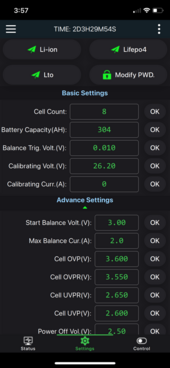
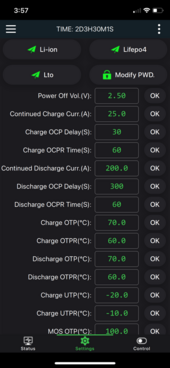
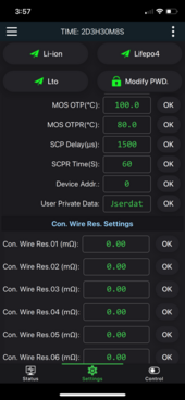
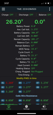
Hey I'm needing some help here. I am building (3) 24v batteries using EVE cells and JK BMS. This is my first DIY battery build and I'm a bit lost in the sauce right now. Basically I have my cells together, BMS connected, app is working but I'm a little lost on how to program the BMS for the cell charging/discharging profiles. I'm used to inputing just Absorption, Float, low voltage cutoff, etc. Below are some screen shots of the JK app. What do I need to program here? (I also haven't charged or discharged anything, also wires were left long during this test phase).

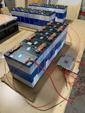
Heres some info on my build:

BMS: JK-B2A8S20P-H-C
Cells: (8) EVE LF304

System will have a 24v Victron Multiplus
IMG_9808.jpeg
IMG_9810.PNG
IMG_9811.PNG
IMG_9812.PNG
IMG_9813.PNG
 
Start Balance Voltage should be increased to 3.4V from 3.0V
Continuous Charge Current can be increased to 75A from 25A.

Keep a log of the BMS settings as a reference when setting up the Inverter.
For example if the if cell OVP is set at 3.60V (which is fine) the maximum charging voltage of the inverter has to be less than 8 x 3.60V.

Edit: IMO the high and low temp protection setting are too wide. Low Temp is usually set to 0 C and High Temp is usually set to 40.5 C (105 F)
 
Hey I'm needing some help here. I am building (3) 24v batteries using EVE cells and JK BMS. This is my first DIY battery build and I'm a bit lost in the sauce right now. Basically I have my cells together, BMS connected, app is working but I'm a little lost on how to program the BMS for the cell charging/discharging profiles. I'm used to inputing just Absorption, Float, low voltage cutoff, etc. Below are some screen shots of the JK app. What do I need to program here? (I also haven't charged or discharged anything, also wires were left long during this test phase).

Heres some info on my build:

BMS: JK-B2A8S20P-H-C
Cells: (8) EVE LF304

System will have a 24v Victron Multiplus
A good starting point is to just copy Andy:

https://off-grid-garage.com/my-settings/
 
On the JK - after you set the # cells, high and low voltage limits, temperature limits (as already discussed) be sure to set:
Calibrating Voltage
Calibrating Current

This is best done with a decent DMM (meter) and a bench charging source,
First without the charger, check the meter reading for pack voltage and set the Calibration voltage to match,
then add a charging source, check the amperage with the meter and set the Calibration Current to match.
 
Wow thanks everyone! I appreciate all the help. I will make these changes.

How do I know what all of the acronyms mean?
 
OCP over current protection
OCPR over current protection return

OTP over temperature protection
OTPR over temperatur protection return

UTP under temperature protection
UTPR under temperature protection return

the pattern continues.
 
OCP over current protection
OCPR over current protection return

OTP over temperature protection
OTPR over temperatur protection return

UTP under temperature protection
UTPR under temperature protection return

the pattern continues.
Ok simply does it!
 
Do my 8 cell voltage leads need to be the same length? I'm seeing the resistance values in the BMS and it got me thinking. I had planned on trimming them once I found my BMS location.
 
In my own experience I find the JK figures out the wire lead resistance anyway so no, you don't need to make them all the same length. Some members disagree, and feel it is just best that the wire leads all be identical - up to you.
 
I cut all mine to whatever length was needed too, which makes it a lot neater, but all my lead resistance figures were pretty low and similar, I imagine it shouldn't make any difference, and if the BMS can sense a major variation then you can check or increase the AWG to fix it anyway.
 
Back
Top