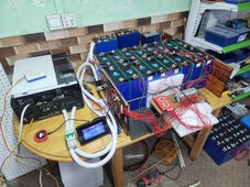
Here's the setup...
2 x 16S LiFePO4 bank
All balancing cables come to a junction block
From that block I have both the JKBMS, & NEEY active balancer
The voltages in the NEEY are spot on, consistent and correct (as per multimeter)
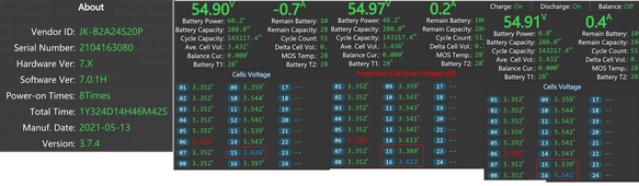
The voltage readings on the JKBMS are jumping around a LOT, by 100mv
See the attached pic, look at 15 & 16. 3 screen shots taken from the BMS app, at most a second apart.
The ~3.54 readings are correct in the last shot, the first 2 shots showing wild readings.
It cant be the bus bars to the terminal blocks, as the NEEY is perfect.
The cables for the NEEY & JKBMS are wrapped together - so it cant be the other side of the terminal block
Is the NEEY balancer interfering with the JKBMS?
The low JKBMS readings i'm thinking it is causing issues, as the NEEY pulling current from the BMS more than the battery.
But why the high readings???
2 x 16S LiFePO4 bank
All balancing cables come to a junction block
From that block I have both the JKBMS, & NEEY active balancer
The voltages in the NEEY are spot on, consistent and correct (as per multimeter)
The voltage readings on the JKBMS are jumping around a LOT, by 100mv
See the attached pic, look at 15 & 16. 3 screen shots taken from the BMS app, at most a second apart.
The ~3.54 readings are correct in the last shot, the first 2 shots showing wild readings.
It cant be the bus bars to the terminal blocks, as the NEEY is perfect.
The cables for the NEEY & JKBMS are wrapped together - so it cant be the other side of the terminal block
Is the NEEY balancer interfering with the JKBMS?
The low JKBMS readings i'm thinking it is causing issues, as the NEEY pulling current from the BMS more than the battery.
But why the high readings???
.jpeg")