diy solar

diy solar

LiFePO Battery internal resistance test

I looked at all the inexpensive units I can find online and all they report is voltage and a number with an ohm symbol or the word ohms after it. Some also report temperature.
None report the resistive component and the reactive component. And no of them even spec the frequency they operate, if they even do operate at a certain frequency.
Check out this 7 thousand unit: Battery impedance meter. This is what they all should do;
BT4560https://www.hioki.com/us-en/products/resistance-meters/battery/id_5897
 
I've used one of those in the past (BT4560)

There not a bad unit and you're right. Those cheep ones don't really tell you everything and it is questionable if they are really impedance meters or just relabled multimeters.
 
These internal resistance testers are not a common multimeter. They are referred to as a four wire type and the standard probe uses two spring loaded gold plated contact points in close proximity at each test point or polarity. From what I’ve gathered it injects a frequency and with an algorithm display a value. In most cases it simply confirms what the manufacturer states. It can identify a ringer, good or bad but and from what I’ve seen the cell are usually better than advertised or matches what’s printed on the label if one is attached.
It can’t determine capacity but it will tell you that the lot will likely have the same performance. Nothing beats a caloric/capacity test. It’s only by happenstance that this meter also gives great conductor resistance values(or reference).

As for a common volt meter, they are only accurate for measuring a battery at two conditions. At full and empty under no load. What’s in between is a very rough guess with that device. View attachment 183585
Yea they're doing some readings identically as the "big industry ones" (which china also probably makes lool).
They have 1 kilohertz frequency that goes into battery using AC
this is what you see in the battery specifications when the battery gets tested at the manufacturer, they will show in the data sheet "xxx ohms tested using 1 kilohertz AC"
I think I saw that here, he's very reputable either way:
not 100% sure though


I didn’t realize that the Chinese have started making inexpensive meters that can measure battery impedance. Sorry for the misinformation in my previous post.
I know plenty of crap comes from china but I do actually appreciate when they copy stuff and make it slightly shittier but 1/10th the cost.

I looked at all the inexpensive units I can find online and all they report is voltage and a number with an ohm symbol or the word ohms after it. Some also report temperature.
None report the resistive component and the reactive component. And no of them even spec the frequency they operate, if they even do operate at a certain frequency.
Check out this 7 thousand unit: Battery impedance meter. This is what they all should do;
BT4560https://www.hioki.com/us-en/products/resistance-meters/battery/id_5897
didn't see this post before but I did answer it above, also video answers it I think
but yea all of the cheap ones literally just read 2 things, voltage and the ohms
 
You could look for a spec sheet for an Eve 200Ah cell for comparison.
Im not sure the resistance measuring devices are necessarily that accurate on these cells. I use dV/dI method

I have been looking for an alternate way to measure the internal resistance of a 280ah Lifepo4 cell besides a device like the YR1035+ Battery Internal Resistance Test Meter. How is the dV/dl method done?

 
Only two ways to check a cell that I know of. The internal resistance is comparable reference and can give an idea of its health, but the last word on a cell is a capacity test.
 
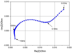
The Impedance of a battery is a function of the frequency used to measure it.

Impedance Characterization and Modeling of Lithium-Ion Batteries Considering the Internal Temperature Gradient

1704310112604.png
There doesn't appear to be any standardized frequency used in the industry. If anyone knows of any standard methods, please respond.
Without any standerdized methods manufactures can use any frequency they want. As mentioned in a few preceeding post, impedance is not a good way to eveluate a battery overall.
 
There doesn't appear to be any standardized frequency used in the industry. If anyone knows of any standard methods, please respond.
Almost every datasheet has 1khz AC as their reference. So while it isn't standardized on paper, nearly everyone does use the same thing.
Also all of the testers do this as well. Haven't even seen any others that do anything else other than 1khz AC
 
Almost every datasheet has 1khz AC as their reference. So while it isn't standardized on paper, nearly everyone does use the same thing.
Also all of the testers do this as well. Haven't even seen any others that do anything else other than 1khz AC
Thanks for the info. The few I looked at all spec 1khz. Ther are many that don't spec any frequency.
 
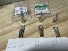
IMG_0235.jpeg

I'm in the process of crimping cables to set up my system and this picture is very helpful as a basis of comparison (assuming those labels on your lugs are what I think they are). @Skypower are those the labels on your lugs and busbars the resistance values of the cables in milliohms? I'm using the same IR tester and I've been trying to determine if my crimps are "good enough" by checking the resistance values, but haven't found much data to compare it to.
 
Those were both resistance and voltage readings. I was looking for correlation or verification of each other, which I found. The resistance was done by using an internal resistance meter and then always using the same location on each lug (the flat between the hole and transition). As a note, the internal resistance meter won’t work if the object you are testing has any load or is in an operating circuit. You can measure through a cell or a conductor, a series of cells, conductors and bms but it can’t be turned ON and connected to a load. (Zero electrical noise!)

The other number was the voltage noted across the cable when I placed a constant load on them. I used a volt meter that could measure down to .XXXX position. I simply put a bunch of conductors in series to my battery bank and set the charge to 100 amp, waited for a few moments for the voltage rise slow down a bit and started measuring. When you run a check like this it gives you pause when you think about every single object and junction is trying to rob you. Breakers, fuses, cables, shunts, bms and buss bars. Taken individually is inconsequential but as a whole, it adds up.
 
I'm in the process of crimping cables to set up my system and this picture is very helpful as a basis of comparison (assuming those labels on your lugs are what I think they are). @Skypower are those the labels on your lugs and busbars the resistance values of the cables in milliohms? I'm using the same IR tester and I've been trying to determine if my crimps are "good enough" by checking the resistance values, but haven't found much data to compare it to.
When you use that meter as such, the levels are so low that you have to use the data for your own purposes and can’t be compared accurately with others. What you are looking for is a “Rogue” or an outlier. Partially or badly crimp one lug and the number will jump out at you. Two things that I noticed were a LIGHT cleaning of the inside of the lug with Scotch bright just to get the surface oxides off and blow out the dust and try to keep the strands straight and not disorganized was the biggest factor.
 
Thanks for the reply Skypower!

When you run a check like this it gives you pause when you think about every single object and junction is trying to rob you. Breakers, fuses, cables, shunts, bms and buss bars. Taken individually is inconsequential but as a whole, it adds up.
This is exactly it! I haven’t put my system into service yet, but as I measure all of these individual components I’m adding it all up in my head, and it’s not nothing.

When you use that meter as such, the levels are so low that you have to use the data for your own purposes and can’t be compared accurately with others. What you are looking for is a “Rogue” or an outlier.

Yeah, I get this. I'm not even looking for an accurate comparison - more about whether I'm in the same ballpark. For example, I have a section of 18" segment of 1/0 with crimped lugs and I measure 0.33 mohm between the hole and the transition. What I've been trying to determine is whether this is "good"? When I measure the resistance on the lugs themselves (from end to end) it's about 0.03-0.04 mohm. According to this chart, 1/0 wire is 0.09827 mohm per foot, so for 18" I would expect it to be about 0.15 mohm. If I add the lugs and the wire together that's 0.23 mohm. So I guess, is 0.05 mohm per lug crimp reasonable/acceptable?

20240413-08-26.38.png
 
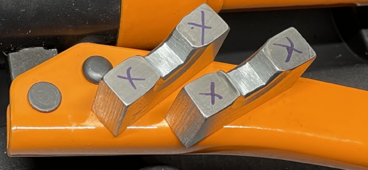
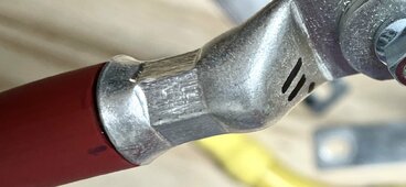
I’m thinking you’re in the ballpark. Considering the smaller cable, longer length and different meter, it’s well within reasonable thinking. The dies that come with the crimpers are pretty much hit and miss as for correctness. If you’re using the correct cable for the lugs, you should end up with crimp with crisp corners on the hex and very little to no extrusion/flash at the die split line. More often than not I’ve modified my dies to work best for the lug brand (Selterm) and size I use (material remove from the area marked X). Adding a small radius on the die corners (not the spit line) can reduce stress and thinning of the lug. I can’t even recommend a brand because of inconsistency. Add to that there is great confusion or inadequate communication regarding what type of lug the die is for. Starter lugs (what most of us use) or power lugs are quite different on the outside diameter. On starter lugs you only need to crimp once. Never rotate and crimp again on a different flat/plain. On power lugs you can crimp two places or more depending die and/or lug size.
IMG_0382.pngIMG_0383.jpeg
 
Back
Top