I can take two identical cells with same FCV. and connect them in parallel as depicted.
The capacity of the combined cell has doubled, The effective IR halved, but the measured FCV or any characteristic voltage for that matter has to be the same. Basic sanity check !!
View attachment 211023
This is very entertaining….
You are proving the above for me. By doubling the capacity you have halved the internal resistance. So capacity and internal resistance are inversely proportional. Yet you demand citations.
I did not say a decrease in internal resistance will change the FCV. An increase will definitively. Something you would see through the addition of a resistor In series. There will be a voltage drop across the resistor be it external or within the battery.
Might as well cite one.
You need to realise that it is a one way street.
For an aging cell, capacity ↓ will indeed cause IR ↑.
But an IR ↑ doesn't necessarily translates to capacity ↓.
Never said it was a two way street. If there existed a technology to restore capacity on a cycled lithium cell. The owner would have more money than Elon.
Think you need to go do some reading. Here is a citation. There are many published works detailing this relationship.
TY - JOUR
AU - Schuster, Simon
AU - Brand, Martin
AU - Campestrini, Christian
AU - Gleissenberger, Markus
AU - Jossen, Andreas
PY - 2016/02/01
SP - 191
EP - 199
T1 - Correlation between capacity and impedance of lithium-ion cells during calendar and cycle life
VL - 305
DO - 10.1016/j.jpowsour.2015.11.096
JO - Journal of Power Sources
ER -
I have said it before.
I am saying again, it is totally common for a cell to have higher internal resistance without affecting measured cell capacity (Ah).
Within the allotted tolerance by the manufacturer. It’s a sliding slope from there.
Not unless current is flowing. But that is not how FCV is determined in the first place.
A voltmeter with infinite resistance does not exist. In order to measure voltage a small current is passed. If we’re getting technical.
In hindsight, The EVE data is still not enough for determining what voltage to float for LFP.
It is sufficient to make an informed decision for Eve cells. You are trying to make a generalised case for all LFP base solely on chemistry now. At the start of the thread it was Capacity. (regardless of Brand, temperature, internal resistance etc).
You are now deflecting and adding technical jargon to resist answering the simple questions asked of your model.
There is no consideration of the surface charge phenomena and how there is a supercapacitor like behaviour at charge end. There is a depletion of vast majority of mobile charge carriers (Li+ ions) too. Not recommended to stay in this region for long.
Again all interesting and will make for great discussion preferably on its own thread. These arguments were not made in your original post.
51.8V-52.5 V comes out to be 3.45 to 3.5 V Cell for 15S battery. That is a dangerous float voltage and is not recommend for even 'grade A' LFP cells due to aforementioned degradation mechanisms.
Typically occurs in economic applications (where price determined the specification) the product won’t be around long enough so it becomes a non issue. Other than high risk telecommunication sites think about charge controls for RC cars, alarm batteries etc.
Sometimes engineering takes the form of planned obsolescence. Quite frankly most times it does where value engineering produces a bridge that barely stands.
This would make an interesting discussion on another thread.
For DIY guys it’s different as we are vested in max cycle life and passionate about cool tech.
Again the term dangerous is so wrong and hyperbole . LFP will not be dangerous under 3,65V. This is not the message to send to guys starting out. We can argue over cycle life protection But there is no risk of fire and this falls within the operating range in the manufacturers datasheet.
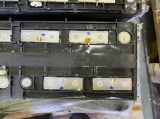
BTW, I have EV Grade A CALB L160F100 Cells with factory QR.
View attachment 211034
Show me your large batches of Eve cells. You have only mentioned these Calb 100Ah cells which is why I say your dataset isn’t large enough to draw such strong conclusions.
I don't get your adamancy. There is simply much more to this that needs to be figured out on your end.
Again deflecting. They are such simple questions that you refuse to answer. Your unwillingness to engage speaks to the lack of confidence in the model. You cannot tell everyone that they are doing everything wrong without being willing to back your argument.
Again. Please answer these simple questions:
So to confirm:
• Does your Method calculate the FCV or do you use the SOC OCV curve from manufacturer?
• Does your method compensate for changes in temperature?
• Does your method calculate the FCV based on capacity alone?
• Do you still think everyone is doing it wrong?