diy solar

diy solar

Microwave seems slow to start

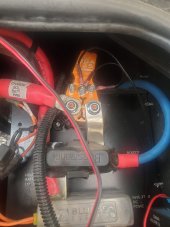
I inspected the wires this morning. The wires tied from battery to battery indicate 4/0 (could only find that specifically on one stamped into the jacket, but all look the same) of "US made Welding cable". The cables leaving the buss bars are 2/0 which go to the Magnum Inverter. I suspect you are correct in that the wire size may have an impact as the cable from the batteries to the buss bar look to be 3 or 4 but I couldn't find markings. I guess I better get some help when I get home to survey whether I have correct wire sizes. So much for hiring a "professional" to do the install for me. 5.0 reviews don't seem to matter any more.

Thank again everyone. Will make do until I get back to home base then try and sort things out there. man there is a lot of cables. Just so I know, is there specific diameters for the cables of 2, 3, or 4 gauge. I couldn't find markings on some of them.
 
The following wire size chart gives the diameter for each gauge. I'm pretty sure the measurements are just the wire, not the insulation.


So you are saying you have 4/0AWG between the batteries, 2/0AWG from the bus bars to the inverter, but only (maybe) 4AWG between the batteries and bus bars? That's really odd.

How long are each of the two 2/0AWG wires to the inverter? As long as they are each 10' or less then they should be fine.
 
Just in case there is confusion
4 awg ~= 35mm2
0 = 1/0 awg ~= 50mm2
00 = 2/0 awg ~= 70mm2
0000 = 4/0 awg ~= 120mm2
 
Last edited:
I am reading a bunch and looking at charts galore. Buss bar is 8 to 10 feet.. Can't get in to see where it goes for sure but that is next. The 4awg between the batteries to the buss bar is about 2 feet. One article I read says this is ok, which is why the installer likely left it from original installation. I still need to audit the amp draw, but can't disconnect from shore power just yet.
 
I am just figuring out 4/0 is really 0000. Marking had 4/0 on jacket but diameter is not that big. That is why later I am going under the coach with dial caliper and tape measure. I know size doesn't include jacket, but at least I will be closer.
 
The 4awg between the batteries to the buss bar is about 2 feet. One article I read says this is ok
What article? On what basis is it determined to be OK? For that length, 4AWG should only be used for up to 100A of load. A 2000W 12V inverter can pull up to 200A from the battery.

And why use 4/0AWG between the batteries and only 4AWG from the batteries?
 
What article? On what basis is it determined to be OK? For that length, 4AWG should only be used for up to 100A of load. A 2000W 12V inverter can pull up to 200A from the battery.

And why use 4/0AWG between the batteries and only 4AWG from the batteries?
This is becoming an Abbot and Costello sketch.
 
I agree. I do not have enough info and am too new to this to ask intelligent questions. I have gained valuable insights from several of you and am humble enough to admit I need to gain way more knowledge. Until I have hard data, let's close this out. Sorry for the inconvenience to everyone.
 
You've left out some very important details in your posts.

What is the wattage rating of your inverter?
2000 watts continuous
What is your battery bank voltage? 12V? 24V? or 48V?
12 volts
What size wire did you use to connect your batteries?
3/0 or better
What size wire did you use to connect your inverter to your battery bank?
3/0 or better
tl;dr 3/0 or better all along the critical path.
 
Under load of microwave 13.15v at battery and 12.75 at inverter. Inverter showed 140 amps. I may have messed up my readings at battery as it was 126 before busbar. Resting voltage before test 13.5
 
Under load of microwave 13.15v at battery and 12.75 at inverter.
That's a 3% voltage drop. That's at the edge of what I would call acceptable. So I wouldn't call that an issue on its own. The inverter should have no issue powering things if it's getting 12.75V.

Inverter showed 140 amps.
If you really have 4AWG between the batteries and bus bar, pulling 140A from the battery is risky. You need at least 2/0AWG, not 4AWG.

I may have messed up my readings at battery as it was 126 before busbar.
Is that a typo? Do you mean you measured 12.6V? For there to be a higher voltage at the inverter than at (or near) the battery there must be power coming in from a charge source such as from solar.

Resting voltage before test 13.5
Battery voltage will drop under heavy load.
 
Last edited:
That's a 3% voltage drop. That's at the edge of what I would call acceptable. So I wouldn't call that an issue on its own. The inverter should have no issue powering things if it's getting 12.75V.


If you really have 4AWG between the batteries and bus bar, pulling 140A from the battery is risky. You need at least 2/0AWG, not 4AWG.
We clarified all cables are 3/0 or larger
Is that a typo? Do you mean you measured 12.6V? For there to be a higher voltage at the inverter than at (or near) the battery there must be power coming in from a charge source such as from solar.
No, that was a concern but @smoothJoey suggested another charge source. Perhaps from solar panels still producing power
Battery voltage will drop under heavy load.
 
We clarified all cables are 3/0 or larger
I guess I'm confused. I saw @smoothJoey post that but I thought he was posting what he thought you needed. Are you two working together so he knows what you actually have?
 
I guess I'm confused. I saw @smoothJoey post that but I thought he was posting what he thought you needed. Are you two working together so he knows what you actually have?
I just helped him answer your questions.
Also thought you would like to see the voltage drop under load.
 
OK then. Given the good size of all of the wiring and sufficient voltage reaching the inverter, why would the microwave misbehave? I've got nothing at this point.
 
Rereading through thread it looks like it’s been ruled out the problem is in the DC side of the system. It doesn’t look like we know the model of inverter? We don’t know if transfer switch is internal of the inverter? We don’t know what the voltage drop is at the microwave is on shore power?
 
Rereading through thread it looks like it’s been ruled out the problem is in the DC side of the system. It doesn’t look like we know the model of inverter?
Magnum Energy 2012 Pure Sine Wave Inverter
We don’t know if transfer switch is internal of the inverter?
External of Inverter
We don’t know what the voltage drop is at the microwave is on shore power?
120.5 resting, drop was to 118.0 with it running (just tested this a.m.)
 
Last edited:
Back
Top