diy solar

diy solar

Microwave seems slow to start

OP has stated to me in DM that the problem is 100% reproducible in inverter mode but does not occur in shore power mode.
@JeffreyD did this problem start when you upgraded your batteries to LFP?
Did you have the BGA 225 battery guard before you got your LFP batteries or at the same time?

Its somewhere between a hunch and a wild guess but I would like to try bypassing the BGA 225 to see if the problem magically goes away.
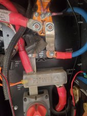
Would some kind soul have a look at the picture and see how practical that is.
 
OP has stated to me in DM that the problem is 100% reproducible in inverter mode but does not occur in shore power mode.
@JeffreyD did this problem start when you upgraded your batteries to LFP?
To the best of my recollection yes. I did not notice the problem on former 6x225ah lead acid batteries
Did you have the BGA 225 battery guard before you got your LFP batteries or at the same time?
Yes, it was added with the LFP/Solar installation
Its somewhere between a hunch and a wild guess but I would like to try bypassing the BGA 225 to see if the problem magically goes away.
If sufficient voltage is getting to the Inverter, would that not have already made it past the BGA 225?
Would some kind soul have a look at the picture and see how practical that is.
Thank you all again.
 
If sufficient voltage is getting to the Inverter, would that not have already made it past the BGA 225?
Probably, but my imagninary friend and his drinking buddy flagged that component as unusual.

Has this problem always existed?
Does the problem pre-date the magnum inverter?
Your magnum inverter is white, confirm?
 
Probably, but my imagninary friend and his drinking buddy flagged that component as unusual.

Has this problem always existed?
No
BDoes the problem pre-date the magnum inverter?
No, inverter is OEM for this coach (2013)
Your magnum inverter is white, confirm?
Yes

Looking at Battleborn's installation guide for the unit compared to the pictures. Advice requested here....it would seem that moving the "Load" side cable to the "Battery" side of the AGM225 would eliminate it from the equation?

Unfortunately, we will be starting out journey home tomorrow, so may go dark on this topic for a week or two until we land again.
 
Looking at Battleborn's installation guide for the unit compared to the pictures. Advice requested here....it would seem that moving the "Load" side cable to the "Battery" side of the AGM225 would eliminate it from the equation?
Yes.

Did the origin of the problem correlate with any system change?
 
Yes, did not notice the problem prior to November 2021 Solar/LFP installation. Was on shore power since then, so did not discover issue until recently when boondocking. AGM225 was installed at same time as Solar/LFP
 
Can you re-take this picture
with the bluesea and bussman shrowds removed?
 
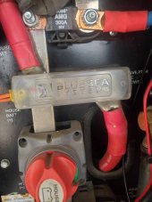
I could not figure out how to get the blue sea cover off so tried to get closeup.20220305_075519.jpg20220305_075525.jpg
 
The cover to the Blue Sea fuse can be removed by squeezing the center of cover at the base. Once you get it off, sand down the plastic prongs a bit. That will make it easier to remove the next time it needs to come off. Mine was very difficult to remove also. Not any more.

I'm not sure what I'm looking at in the picture. Is the big red wire on the right (going through the hole) the wire to the inverter? If so, it makes me wonder what the small two orange wires and the big red wire on the left of the Blue Sea fuse are going to. They seem to have no fuse protection.
 
Orange wires have fuses (you can see one in top pic). Left cable to batteries, right to inverter.
 
Orange wires have fuses (you can see one in top pic). Left cable to batteries, right to inverter.
Most of the wires in bga 225 picture look smaller than 3/0 awg.
The only one that looks 3/0 or larger is labeled "charge, sol, batt, pwr".
It is connected to the bga 225 bat position so I figured it went to the main battery positive.
No you are saying the red wire that comes off the left side of the Bluesea device is heading to the battery.
I'm going to take a step back because I'm a bit frustrated.

Anyways this is a job for someone with keen vision.
 
Agreed. Let's close out this discussion. I have learned much and do not want to wear out my welcome.
 
Agreed. Let's close out this discussion. I have learned much and do not want to wear out my welcome.
You won't were out your welcome. You should try a better picture where all of the wires can be seen instead of such closeups.

It is a small area to try to get great pictures but overlap a little so wires can be followed from one pic to the next.

It almost looks like the red cable from the batteries connects to a bussbar were the 300a fuse/ bluesea fuse and then the madter on/ off switch, leave the other side of the master switch but no more picture to follow.

My personal feeling is that the batteries are wired poorly and the installer should of given it more thought. This is were 2 larger capacity batteries are better than 4 smaller.
 
Thank you. We landed for the night in a camping world parking lot. May not get to this right away, but will eventually.
 
I inspected the wires this morning. The wires tied from battery to battery indicate 4/0 (could only find that specifically on one stamped into the jacket, but all look the same) of "US made Welding cable". The cables leaving the buss bars are 2/0 which go to the Magnum Inverter. I suspect you are correct in that the wire size may have an impact as the cable from the batteries to the buss bar look to be 3 or 4 but I couldn't find markings. I guess I better get some help when I get home to survey whether I have correct wire sizes. So much for hiring a "professional" to do the install for me. 5.0 reviews don't seem to matter any more.

Thank again everyone. Will make do until I get back to home base then try and sort things out there. man there is a lot of cables. Just so I know, is there specific diameters for the cables of 2, 3, or 4 gauge. I couldn't find markings on some of them.
What's the voltage sagging to at the microwave plug?
 
I tested voltage and got 122v resting. With microwave on it dropped initially to 111, the stabilized at 115. Hot pot drops to 115 then stays at 118. Weirdly, My espresso machine was the worst as it pulled to 108, then bounced between 109 and 120 as various pumps worked.
The picture is my battery set up. I clamp tested plus and minus and got different results on all. Not sure I am doing this right.
Here is that info
 
Back
Top