


You are using an out of date browser. It may not display this or other websites correctly.
You should upgrade or use an alternative browser.
You should upgrade or use an alternative browser.
MPP LV6548 Build
- Thread starter DanF
- Start date
Sanwizard
Solar Wizard
- Joined
- Feb 2, 2021
- Messages
- 2,715
Just saw your latest video. I left a comment. Love that you gave props to DMI and Andy! So after that capacity test, did you check individual cell voltages to see if you are still balanced? You said you dont use a BMS, only balancer, so I am interested to see if the parallel LV6548's charge them up properly, and they stay balanced.
Sanwizard
Solar Wizard
- Joined
- Feb 2, 2021
- Messages
- 2,715
Just noticed the cell wire resistance in your picture. Did you use different wires than what came with your bms? My resistance is much higher. Any thoughts?53. You got me wondering so I just reversed and went into charge mode. I will report results here soon.. but the picture shows just before transferring from discharge to charge
Sanwizard
Solar Wizard
- Joined
- Feb 2, 2021
- Messages
- 2,715
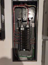
I am also interested in your wiring diagram, especially how you tied everything back to your main. Can you explain your wiring in this pic of yours? I am not familiar with red black white and green. I assume green is ground, and white is neutral. Are the thick red and black L1 and L2 from the inverters?Do you have a wiring diagram?
It would be interesting to do some math on the currents on L1, L2, N, and compare with G, to confirm that G is load-sharing N.
You also have both red and black on each leg in the panel. Whats with that? Load balance?
Attachments
Sanwizard
Solar Wizard
- Joined
- Feb 2, 2021
- Messages
- 2,715
Hey Dan, hope you dont mind a quick question. I know you are an electrician, and code differs state to state, but my question is more general.I couldn't help myself... everything arrived today except for the fuse.. I put a "fusible link" in. I had to see them light up! WOW, THIS IS SOOOO COOL! Running a true capacity test now... Boy, those LED's are pretty..
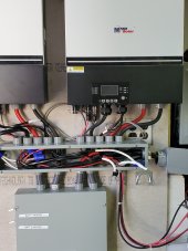
I am using 4awg wire like the manual states for the AC side of the inverters, and am running a black phase from one inverter, and a red phase from the other to a manual knife disconnect on/off/on switch. There is only room for one neutral in the switch for input. My question is how do I connect the 3 x #4 neutral wires together? One neutral from each inverter going to a single connection into the switch?
You can see my three white wires hanging out of the cable trough. Home depot and Lowes have nothing, and online, all I see is 600V rated connectors.... do I use a large bus bar? Is that code? Any advice appreciated. How did you tie your neutrals together?
Sanwizard
Solar Wizard
- Joined
- Feb 2, 2021
- Messages
- 2,715
Hey Dan, hope you dont mind a quick question. I know you are an electrician, and code differs state to state, but my question is more general.
I am using 4awg wire like the manual states for the AC side of the inverters, and am running a black phase from one inverter, and a red phase from the other to a manual knife disconnect on/off/on switch. There is only room for one neutral in the switch for input. My question is how do I connect the 3 x #4 neutral wires together? One neutral from each inverter going to a single connection into the switch?
You can see my three white wires hanging out of the cable trough. Home depot and Lowes have nothing, and online, all I see is 600V rated connectors.... do I use a large bus bar? Is that code? Any advice appreciated. How did you tie your neutrals together?
Attachments
I used- Morris 97513 3 Conductor Single Side Entry Splice from Jackson electric supply (on the internet) My wires are #6, but they might have those in #4 as well.. Home Depot and Lowes carries them as well, but they were over double to triple the price!

Sanwizard
Solar Wizard
- Joined
- Feb 2, 2021
- Messages
- 2,715
Yay! That is exactly what I ordered from Amazon.I used- Morris 97513 3 Conductor Single Side Entry Splice from Jackson electric supply (on the internet) My wires are #6, but they might have those in #4 as well.. Home Depot and Lowes carries them as well, but they were over double to triple the price!
View attachment 55221
Lt.Dan
Solar Wizard
I am also using the same thing. I bought them at a local electrical shop for about $15 ea
Sanwizard
Solar Wizard
- Joined
- Feb 2, 2021
- Messages
- 2,715
Yes, these look like a much better solution than large wire nuts. I used the big purple wire nuts for the 3x #6awg for the ac input, but since I used #4awg on the outputs, they did not fit. I may order a few more and redo the #6awg connections. Thanks guys!I am also using the same thing. I bought them at a local electrical shop for about $15 ea
I have the lv6548 and I cannot get connected to the APP drop you have any suggestions that I can try, the manual way of using the LCD screen is getting a bit annoying when trying different settings.The app is okay.... it works well for changing the settings on the inverters but you really need to study the booklet before connecting the inverter/inverters. The app also is nice for checking in on what's happening with your setup. It was a bit tricky setting up the wi-fi on them.
Sanwizard
Solar Wizard
- Joined
- Feb 2, 2021
- Messages
- 2,715
Please provide what your issue is. You need the wifi app, not bluetooth. The wifi ID usually starts with W08xxxxxxxx.I have the lv6548 and I cannot get connected to the APP drop you have any suggestions that I can try, the manual way of using the LCD screen is getting a bit annoying when trying different settings.
Download the wifi app to your phone. Then use the wifi search to find and connect to your inverter. (You should have your home wifi also available so you can connect to it from the app once you link the inverter wifi to your home wifi.)
The manual is pretty good to walk you through the process. The default password for watchpower is administrator( all lower case).
Hey Dan, take a look at the IronRidge XR Rail system, excellent engineering and a bonded grounding system. I just DIY installed the rail system and 36 Mission Solar 350w panels. It was my Covid "vacation" project! I did finally get my 15 yr old son to help me set & wire panels on the 2-story roof. If you have some time it's not that tough to do, a ton of info on YouTube/Internet. Here in N. Calif, I searched a 100 mile radius and all the installers were 3-4 months booked out! Photos also show my Enphase micro inverters with 1/2in EMT and metal junction boxes. https://www.ironridge.com/pitched-roofs/
So I think I have it figured out I was trying to connect it to my 5 GHZ WiFi and the built in WiFi is only 2.4 GHZ so it would not connect. When I connected it to the 2.4 network it worked fine. Thank You for the assistance.Please provide what your issue is. You need the wifi app, not bluetooth. The wifi ID usually starts with W08xxxxxxxx.
Download the wifi app to your phone. Then use the wifi search to find and connect to your inverter. (You should have your home wifi also available so you can connect to it from the app once you link the inverter wifi to your home wifi.)
The manual is pretty good to walk you through the process. The default password for watchpower is administrator( all lower case).
V/Tim
Sanwizard
Solar Wizard
- Joined
- Feb 2, 2021
- Messages
- 2,715
I really like the way these inverters leverage available power. I still have mine in parallel, and noticed one was pulling 845 watts from its PV string, and the other was sitting at 45 watts, and it has the exact same string config of panels. I thought something was wrong, so I turned on the lights, and it shot up from 45 to 900 watts. I then noticed the light breaker is on the same phase as the inverter that was sitting at 45 watts. (Battery was fully charged at this point)So I think I have it figured out I was trying to connect it to my 5 GHZ WiFi and the built in WiFi is only 2.4 GHZ so it would not connect. When I connected it to the 2.4 network it worked fine. Thank You for the assistance.
V/Tim
I turned on the AC, and then the other inverter shot up to 1200 watts.
Pretty cool how that all works.
HGPilot
New Member
- Joined
- Nov 29, 2021
- Messages
- 33
Starting the build.. 16-272a Lifepo4 cells, 2- MPP LV6548 Inverters in 240v operation. Solar TBD...View attachment 33397
My dream install
Outstanding quality work!
I am in a process of building exactly the same setup, waiting for batteries and the inverter to arrive...
I have a question about Ground bonding to Neutral at the generator requirement and Ground bonding to Neutral at your main AC output panel and how you solve this dilemma?
My generator calls for grounding and by code you have to ground at your main panel but that would create a ground loop I am afraid.
What happens when generator is not running or completely disconnected? How do you switch between those modes?
May I also ask what kind of generator are you using and how big is it? I am looking at an Inverter Generator Energizer EZV8500EFI but it can only output 54Amp@120V 6800W at 100%....
Thank you!
A
DanF, nice work, I am building a single LV 6548 system with 20 sealed AGM batteries. I am a William Prowse student, as I understand it he says that a cutoff or breaker is not necessary on the battery to inverter side and you agreed. MPP mentions putting in over current protection and disconnect, I want to protect my investment as priority. Following William I will be using battery balancers and then straight 48V into inverter, am I getting that right?
raurre
Solar Enthusiast
I have recently built a lv6548 system. I have posted a lot of pictures on the show and tell section. I used a class t 300 amp fuse to provide over current and short current protection. I could not find any piece of equipment that seemed optimal for disconnect. In the event of a real problem the fuse will disconnect the system for you.DanF, nice work, I am building a single LV 6548 system with 20 sealed AGM batteries. I am a William Prowse student, as I understand it he says that a cutoff or breaker is not necessary on the battery to inverter side and you agreed. MPP mentions putting in over current protection and disconnect, I want to protect my investment as priority. Following William I will be using battery balancers and then straight 48V into inverter, am I getting that right?
Last edited:
Thanks, earlier in this thread you can see Williams response on the battery to inverter side, isn't the T 300 fuse to protect the PV panel to inverter connection from lightening? I will look at your photo's. CheersI have recently built a lv6548 system. I have posted alot of pictures on the show n tell. I used a class t 300 amp fuse to protect over current and short current protection. I could not find any piece of equipment that seemed optimal for disconnect.
Sanwizard
Solar Wizard
- Joined
- Feb 2, 2021
- Messages
- 2,715
Putting a cutoff switch between the battery and inverter provides a measure of safety, and enables easier maintenance. Make sure to also use a pre-charge resistor when first applying battery power to an inverter that was powered down. The manual is correct. Will sometimes creates test environments to play with. They usually are not permanent installations.DanF, nice work, I am building a single LV 6548 system with 20 sealed AGM batteries. I am a William Prowse student, as I understand it he says that a cutoff or breaker is not necessary on the battery to inverter side and you agreed. MPP mentions putting in over current protection and disconnect, I want to protect my investment as priority. Following William I will be using battery balancers and then straight 48V into inverter, am I getting that right?
Sanwizard
Solar Wizard
- Joined
- Feb 2, 2021
- Messages
- 2,715
There are DC switches available that are rated for over 48V and high amps. Check a marine supply. Blue Sea DC switches are NOT rated for over 48V. Amazon has quite a few that should work.I have recently built a lv6548 system. I have posted alot of pictures on the show n tell. I used a class t 300 amp fuse to protect over current and short current protection. I could not find any piece of equipment that seemed optimal for disconnect.
Similar threads
- Replies
- 1
- Views
- 175
- Replies
- 17
- Views
- 808
- Replies
- 1
- Views
- 298
- Replies
- 2
- Views
- 135
- Replies
- 4
- Views
- 245