diy solar

diy solar

Multiplus II Bypass Switch

BipedalPrimate

New Member
Joined
Mar 25, 2022
Messages
61
Happy New Year to all you good people.

Planning/designing a Grid Tied ESS with Victron & DIY LiFePO4 to maximise self consumption.

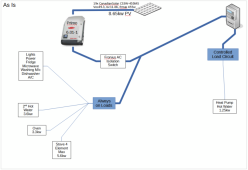
This is the current state:
1672555838089.png

(Don't be too critical - the Heat Pump Hot Water was installed whilst I was in Europe & the installer simply replaced a 5kw Tank Hot Water system without thinking that it was on a Controlled Load Circuit. It was free upgrade - in Victoria, Australia. Works quite well but only between 11pm & 7am.)

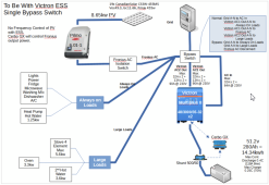
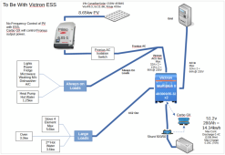
This is the desired end state:
1672556384811.png

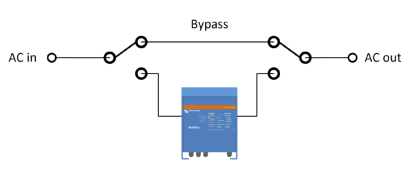
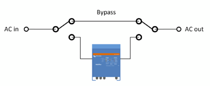
Victron (via their Wiring Unlimited guide) & others recommend that a Bypass Switch be installed to isolate the Multiplus II as follows:

6.6 AC bypass switch
It is recommended to add a manual bypass switch to an inverter/charger system. This is especially useful in mission critical systems. This switch allows you to bypass the inverter/charger and will connect the AC input (grid or generator) directly to the loads.
A switch like this will prove invaluable in case the inverter/charger needs a configuration change or should anything go wrong with the inverter/charger and it needs to be removed for service.
The bypass switch will need to break the AC in and AC out path to and from the inverter/charger and it then needs to make the bypass circuit. The switch needs to be rated to the full AC load of the system.
1672556671716.png

Very useful advice BUT:
  1. Notice in the To Be diagram above that the Fronius AC Inverter is connected to the AC1 Out of the Multiplus II
    Maximum allowable feed in here is 5kw.
    If Bypass Switch is used as per diagram, risk of feeding in 6kw exists - not a discussion I wish to have with the electricity distributor here.
    To manage that limit, there is a Fronius Smart Meter installed between the Grid and the Fronius AC Inverter in the As Is diagram above - it is not shown.
    That Fronius Smart Meter must be removed when connecting the Fronius PV Inverter to the AC1 Out of the Multiplus II.
    The Cerbo GX manages the output limiting of the Fronius PV Inverter via MODBUS TCP.
  2. Further to 1, if we leave the Fronius PV Inverter outside the scope of the Bypass Switch and remaining connected to Multiplus II AC1 Out, there will still be 230v with variable current (depending on battery SOC & idle current) going to the Multiplus II.
    The Fronius AC Isolation Switch could be used to disconnect but someone needs to remember to do that before touching anything.
  3. There are two AC Out connections on the Multiplus II.
    Both will need to be switched by the Bypass Switch.
  4. Under normal situations with the Grid active, there is an Earth-Neutral connection in the switchboard.
    The Multiplus II maintains that connection to that single Earth-Neutral connection until the Grid fails.
    On Grid failure, the Multiplus II then disconnects the AC In (A & N) and creates its own Earth-Neutral connection internally.
    (In Australia, the tendency is to use the word Active rather than Live as in Active Conductor instead of Live Conductor)
    When Bypass Switch is used, both A(ctive) & N(eutral) will need to be switched to ensure there is an active Earth-Neutral connection in the circuit. That is, cannot leave the Neutral conductor connected to the Multiplus II.
These are the constraints & assumptions that will be used to configure a single Bypass Switch.

This is what I have come up with:
1672559064419.png

So, does a Bypass Switch exist that can handle this number of circuits/conductors?

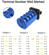
Others on this site have suggested the VictorsHome Changeover Switch LW28-63 3 Positions 16 Terminals.

They provide a diagram of how it switches as follows:
1672560083760.png

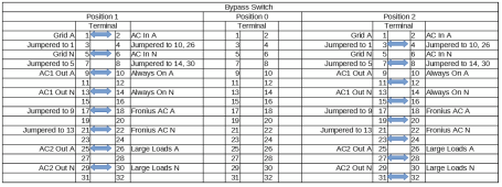
When I try to map the required switching functions to this type of switch, it seems I need 32 terminals - not 16.
1672560408771.png

My questions to the wisdom of this crowd are:-
  1. Have I made any incorrect assumptions?
  2. Am I overthinking what needs to happen?
  3. Are there any alternatives to VictorsHome Changeover Switch that will do the job?
  4. Are there other solutions (other circuit switching devices) that will work?
  5. Other comments welcome.
Preference is for a single switch/one user action to perform the Bypass functions as my daughters have already asked how long the training course is to use and manage the complexity of the whole Victron ecosystem. :)
 
Ac in on multiplus-ii can flow electricity both ways, simply use the Ac in only.
With ESS the multiplus switches off if Ac in fails, thus there will be no power flowing through it to ac 1 or Ac2 out.
 
Personally I would do it with a couple of two pole relays. One for each loads output. To bypass both inverters. They could be automated or controlled manually by a switch. (Or both)
 
Ac in on multiplus-ii can flow electricity both ways, simply use the Ac in only.
With ESS the multiplus switches off if Ac in fails, thus there will be no power flowing through it to ac 1 or Ac2 out.
My understanding is that with ESS when the Grid fails, the Multi will try to provide the load on AC 1 Out from battery or PV on AC 1 Out.

So I not sure I understand what you mean.
 
Personally I would do it with a couple of two pole relays. One for each loads output. To bypass both inverters. They could be automated or controlled manually by a switch. (Or both)
Could you provide a simple block diagram that shows how this would work?

As you may have gathered from OP, I get a better sense of things with pictures.
 
Could you provide a simple block diagram that shows how this would work?

As you may have gathered from OP, I get a better sense of things with pictures.
Same as this but with the grid-tied inverter also on the bottom with the victron, for the non critical loads.
1672569078605.png
 
The relay will have a common (C), normally open (NO),and a normally closed (NC) terminal.
The load connects to the "C". The inverter output connects to the "NO". The grid connects to the "NC".
The relay coil is powered by the inverter output. And a switch can be added between the inverter output and the coil.
 
Please also take a look at this document from Victron about the factor 1 rule when connecting a PV installation on the AC-out.
https://www.victronenergy.com/live/ac_coupling:start

Another consideration is to purchase one Multiplus II GX, you then have the cerbo integrated in the multi and don’t need a separate GX/verbod device. It saves wiring
Yes the Factor 1 rule has been considered is which why there are two Multis in parallel to give a total of 6kw on AC1 Out.

Also I had considered a Multiplus II GX but decided to go with a RPI based Venus GX because I like the challenge ( :) ) and wanted a separate device for flexibility. One of the requirements of Victron Mutis in Parallel is that the devices must be same/similar in terms of manufacturing date, firmware, capacity which I could not be confident of if one was a Multi GX.
 
Last edited:
Same as this but with the grid-tied inverter also on the bottom with the victron, for the non critical loads.
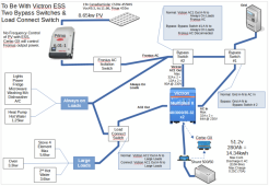
So something like this:
1672616163322.png
With this wiring:
1672616938315.png
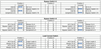
And these steps to enable Bypass:
1672616824341.png
The benefit of the Load Connect Switch separate from the Bypass Switches is that in the event of Grid failure, the Multiplus II will disconnect AC2 Out but it gives me the choice based on expected PV and battery SOC to reconnect the Large Loads if warranted.

Thanks for your thinking on this.
 
No
Much simpler.
The bypass relay chooses between feeding the load from the grid or the inverter.
 
Yes the Factor 1 rule has been considered is which why there are two Multis in parallel to give a total of 6kw on AC1 Out.

Also I had considered a Multiplus II GX but decided to go with a RPI based Venus GX because I like the challenge ( :) ) and wanted a separate device for flexibility. One of the requirements of Victron Mutis in Parallel is that the devices must be same/similar in terms of manufacturing date, firmware, capacity which I could not be confident of if one was a Multi GX.
I seen you are using 2x multis, I was also thinking about the situation where one would fail and the other is still functional. Maybe consider some hardware to automatically switch off the Fronius in case of failure of one of the multis. But maybe I’m overthinking this to much.

I have Venus OS running on a RPI 3B+ for 3 months in my camper. I found the software to function reliable only I loos sometimes the connection with some devices (2x MPPT, 1x Multiplus, 1xsmartshunt). I suspect this is due to grounding issues or coupling on the 24vdc lines and USB lines As it always happens when my water pump switches on which is about 15amps. Something to consider to use well shielded lines and route them separate from the power cable’s.
Also consider to use a SSD Hard drive instead of an SD memory card. I have been running a domotica (Domoticz) on a RPI for the last 6 years and I had many SD card failures since they don’t last to long when used 24x7. on average I failed the SD cards after 14 months since new.
Now I use a SSD HD connected to one of the USB ports, apparently this will last longer.
 
In Australia the N out of the inverter must be connected to the installation N. The grid N must not be broken in Australia. It is different to other countries. Also the Earth out of the inverter is not to be used.
There is a setting in the MP2 ESS Confog for how the N is bonded.
Also the loss of mains is done by frequency detection.
Be weary about this type of setup as the MP2 is not on the approved list for grid grid connection with the new 4777.2 rules. See clean energy council.
Using AC OUT 1 for critical loads and having a bypass switch the selects grid or mp2 is a good idea. The grid neutral must not go through the bypass switch.
Using AC2 for non critical loads introduces more wiring changes as they will be only fed from the grid. If you leave them connected as per normal it will make bypassing the MP2 in case of failure easier.
There is a good wee branded unit that has a really good drawing of how this is wired up. Can be applied to the mp2 as well. I'll try and find the link..
The only thing I am not sure of is the ac inverter on the ac 1 out. If i was doing the setup I would have the relay output of the cerbo controlling a contactor that had the HWS switching between the AC2 out of the mp2 and the Controlled load circuit. I believe that there needs to be a place to dump excess power from the a 1 out side of the inverter if the load drops suddenly and the inverter cannot adjust output fast enough and the batteries are full.
 
The grid N must not be broken in Australia.

I did ask a Licensed Electrical Inspector about switching the Neutral downstream of the MEN link & he said it was OK provided continuity with the MEN link was maintained.

In the Victron VE Config software, I would be selecting the Grid Code 'Australia A - No N-Bypass' which maintains continuity to the MEN link through the Multiplus when the grid fails. Without the No N-Bypass option the Multiplus would break/open both Active & Neutral on AC In when grid fails. With the No N-Bypass option the Multiplus only breaks/opens the Active on Ac In when grid fails.

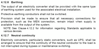
This extract from the Wiring Rules suggests maintaining connection to the site MEN link is required - of course.
1680521291076.png
I do recall seeing something in the Wiring Rules about not switching the Neutral but I can't find it now - do you have it?
 
As far as i am aware, the grid neutral does not get switched at any time, no matter where the supply is coming from unless it is a 2 pole breaker rcd.
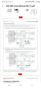
I know this is from a different brand of inverter but the pic shows the N out being bonded to the main installation N. The thing I do know about N being switched is that they must be made first and broken last as per the AS..
If you select N externally bonded in the settings it would not matter what happens with the N connection inside the MP2 but it does impact how the MP2 reacts to supply coming from something that does not have an MEN.
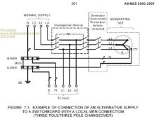
That last line you mentioned.. I read it as the N does not get switched at all or no matter what the device does the N does not get interrupted...
I am yet to test a line interactive ups to confirm the setup. Essentially what you are building is exactly that.. A line interactive ups.
I am not sure if that helps or hinders..
I am am going through the motions of selecting an inverter myself and I have not gone through the exact details for the N, only seen things like the pic I shared.
When you compare connecting an inverter up to connecting a generator up it makes sense. When you connect a genny, the grid A gets disconnected but the N does not.
 

Attachments

  • Screenshot_20230405_123521_Edge.jpg
    Screenshot_20230405_123521_Edge.jpg
    195.1 KB · Views: 18
  • OIP.jpeg
    OIP.jpeg
    28 KB · Views: 16
Back
Top