diy solar

diy solar

My DIY LiFePo HV Battery Build

notts

New Member
Joined
Dec 31, 2022
Messages
12
Have decided to add extra storage capacity to existing system by using a HV LiFePo battery system. This has been a thought for a while but lack of a reasonably priced HV BMS has prevented it . The new Heltec HV BMS looks ideal for this build. Heltec BMS link
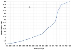
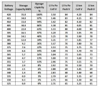
Cells will be 50 Ah with 5 packs of 24S making 120S in total or 420V in total for 3.5V/cell fully charged. The capacity will be 19.2 kWh. This new battery will be paralleled with my existing LiIon pack comprising of 100S 10P using 50E cells which has identical fully charged total voltage of 420V. My current hybrid inverter has a maximum battery charge voltage of 420V and a low voltage cut-out of 315V which equates to 2.63V for the new HV LiFePo battery.
Attached is the basic schematic diagram of the new battery . All bits have been ordered from China with some arrived . Happy to discuss the schematic concepts if any queries.

This is not a build that people should follow unless they fully understand HV DC risks and equipment considerations.

I will add posts during the build any any issues that arise.

Cheers from sunny Perth Australia
 

Attachments

  • 120S Schematic Diagram Rev 3 22 September 2023.pdf
    526.2 KB · Views: 47
I now have a 100v thirty cell system.
Not anywhere near as ambitious as yours, but it has some both good and bad features.
The good features are much thinner wiring and much lower losses.
The bad features are more cells start to become much more difficult to monitor and balance, and arcing of electrical contacts can become an issue.

I did run an experimental 240v dc system a few years ago (without a battery) and decided the advantages did not outweigh the dangers and potential problems so went down to 100v. My own personal experience suggests a practical maximum design current of 100 amps and voltage of 100v arguably offers the best balance of performance and safety, with the least cost and potential issues.
 
Last edited:
Last edited:
I now have a 100v thirty cell system.
Not anywhere near as ambitious as yours, but it has some both good and bad features.
The good features are much thinner wiring and much lower losses.
The bad features are more cells start to become much more difficult to monitor and balance, and arcing of electrical contacts can become an issue.

I did run an experimental 240v dc system a few years ago (without a battery) and decided the advantages did not outweigh the dangers and potential problems so went down to 100v. My own personal experience suggests a practical maximum design current of 100 amps and voltage of 100v arguably offers the best balance of performance and safety, with the least cost and potential issues.
yes -having a max charge current of only 7.5A means a lot less losses and less copper . my battery is about 20m away from inverter so a hv battery is better suited

The heltec hv bms has an active balancer for cells within each 24S packs so should look after any drift over time
I will top balance all cells before putting into service
 
Certainly do able.
But switches, circuit breakers, and plugs will likely become a reliability issue.
Once a dc arc starts up, there is really no way to stop it.
 
Certainly do able.
But switches, circuit breakers, and plugs will likely become a reliability issue.
Once a dc arc starts up, there is really no way to stop it.
not really - just use 1000V rated PV DC fuses for protection and a proper 1000V DC rated circuit breaker for isolation and protection back-up . There are no plugs on the HV battery output . These are very common components
 
Interesting build, looking forward to seeing the progress. If you've got the skills to build it right, and with safety in mind, it should be fine. Cars run at 400 and 800 volts DC in a much worse environment.

What is the 84 volt socket on the left?

I'm guessing the green box is a multi pole switch that when open splits the pack up into multiple (lower voltage) sections?
But the more I look look at it, I think you connecting each 24v pack in parallel to the 84 volt charge socket? But, not disconnecting the series string? That's multiple direct shorts!

Also, are you using that exact socket? Are they rated for DC voltage? I've never looked, but I've got my doubts.

What is the purpose of the 5v buck with each 100 volt display?
The 84V socket and the pack charging selector switch are designed to be able to individually charge 1 of the 5 packs if there is a substantial out of balance amongst the packs. I have not had to use this to date and it would be a very infrequent need - maybe once a year! . The selector switch connects the input charger socket 84V to any one of the five packs . It is a five position double pole switch ( 1 for +ve and 1 for -ve) . There are no multiple direct shorts!. The 5V buck converters are there to simply supply 5V to the digital voltmeters.
 
The 84V socket and the pack charging selector switch are designed to be able to individually charge 1 of the 5 packs if there is a substantial out of balance amongst the packs. I have not had to use this to date and it would be a very infrequent need - maybe once a year! . The selector switch connects the input charger socket 84V to any one of the five packs . It is a five position double pole switch ( 1 for +ve and 1 for -ve) . There are no multiple direct shorts!.
Ah, cool
The picture looks like it's only 2 position.
The 5V buck converters are there to simply supply 5V to the digital voltmeters.
?
 
Attached graph shows approx. storage capacity for various combined pack voltages . The system is not designed or intended to share load equally between the Li Fe Po and the Li Ion packs. Both of these can handle the full load discharge current of approx 15A (5000W). The Li Fe Po takes most of the load ( 80%) between 380V and 400V whilst the Li Ion packs take up most of the load below 380V . Opposite of course for recharging
 

Attachments

  • Capacity Test.jpg
    Capacity Test.jpg
    67.5 KB · Views: 6
  • table.jpg
    table.jpg
    129.9 KB · Views: 5
Ah, cool
The picture looks like it's only 2 position.

?
no worries - I think the image on the schematic was all I had at that time . image shows the actual switch with terminal nos corresponding to schematic
 

Attachments

  • switch.jpg
    switch.jpg
    161.2 KB · Views: 11
Back
Top