diy solar

diy solar

Mystery AC stray voltage on PV wires/frames

pre176

New Member
Joined
Nov 15, 2022
Messages
5
I am helping my father install a 16 panel 6.4kW off grid ground mount system at his house in the Bahamas. These are setup as 4 individual strings (~190Voc, 10A), eventually feeding 2 LV6548 MPP Solar inverters in a split phase setup. At the moment, only one inverter has been installed and is operating, with 2 of the strings feeding each of its CCs. While doing work around the panels shortly after installing them and connecting them for the first time, my father noticed he was getting a light to moderate shock from the frames of the panels, and from what I understand the frame registered an AC voltage to ground on the multimeter (~50-60V from what I am told). He has since installed a ground rod at the array location and connected the frames to it, which has allowed that stray voltage on the frames to go away. However, the unused and unterminated wire runs (#10 THWN) that will in the future be connected to the other strings have also since delivered the same shock, and are also registering an AC voltage. These are in the same conduit as the active wire runs for ~80 feet. There is no grid power anywhere near the house or array or anything else in the conduit with the PV wires. So apparently they are picking up AC induction from the in-use PV wires - which still doesn't answer why the frames were somehow energized at one point or why AC is present in the first place.

On the AC side, the LV6548 is the location of our neutral-ground bond, with the bonding screw removed from the main power panel where the ground from a separate ground rod is referenced. There must be some sort of stray AC voltage getting onto the DC side of the inverter. I've seen a few references to people being shocked on the frames or perhaps AC induction from grid sources, but nothing that quite matches with this scenario. Does anybody have any idea of what could be going on?

Both my father and I are electrical engineers, btw. So we have some competence in this space, for better or worse.
Probably not the correct answer but I had stray AC at our cabin for a while that had me scratching my head. Turned out to be leakage from the utility lines nearby that went away when the utility got on top of.
 
What's the frequency? Can you shut down the inverter and still see the voltage? Do you have another load you can put on the panels with the inverter off? A properly sized resistance should do it.

Do you have any connection between the string wiring and the panel frames? Where are the panels installed? Roof, frames on ground etc? Have you tested for leakage between the panel wires and their frames?
 
LV6548, as most of the cheaper HF inverters, PV input terminals are not electrically isolated from AC PWM chopper in inverters.

The PV input terminals to AIO HF inverter are riding on top of a 60Hz 250v square wave (for a 120vac HF AIO inverter). This is why you must use double pole breakers to PV pos and neg wires on these inverters.

If PV panels have any leakage resistance between their PV wires and frame of PV panels you will get some leakage from AC square wave. In a salty air environment this may happen.

With everything shut down and PV wires unplugged, check resistance from pos and neg PV panel lines to frame of panel. Infinity resistance would be nice but should be at least greater than 200k ohms.
 
Last edited:
I am helping my father install a 16 panel 6.4kW off grid ground mount system at his house in the Bahamas. These are setup as 4 individual strings (~190Voc, 10A), eventually feeding 2 LV6548 MPP Solar inverters in a split phase setup. At the moment, only one inverter has been installed and is operating, with 2 of the strings feeding each of its CCs. While doing work around the panels shortly after installing them and connecting them for the first time, my father noticed he was getting a light to moderate shock from the frames of the panels, and from what I understand the frame registered an AC voltage to ground on the multimeter (~50-60V from what I am told). He has since installed a ground rod at the array location and connected the frames to it, which has allowed that stray voltage on the frames to go away. However, the unused and unterminated wire runs (#10 THWN) that will in the future be connected to the other strings have also since delivered the same shock, and are also registering an AC voltage. These are in the same conduit as the active wire runs for ~80 feet. There is no grid power anywhere near the house or array or anything else in the conduit with the PV wires. So apparently they are picking up AC induction from the in-use PV wires - which still doesn't answer why the frames were somehow energized at one point or why AC is present in the first place.

On the AC side, the LV6548 is the location of our neutral-ground bond, with the bonding screw removed from the main power panel where the ground from a separate ground rod is referenced. There must be some sort of stray AC voltage getting onto the DC side of the inverter. I've seen a few references to people being shocked on the frames or perhaps AC induction from grid sources, but nothing that quite matches with this scenario. Does anybody have any idea of what could be going on?

Both my father and I are electrical engineers, btw. So we have some competence in this space, for better or worse.
Did you ever figure out if it was AC induction on the unterminated wires? I'm having a similar issue and trying to troubleshoot the problem.
My lvx 6048 seems to put out AC voltage everywhere. I measured 100v AC voltage from L1 L2 to my garage door track, I also measured 83V AC to a random 5ft piece of wire not attached to anything.
Is this only when its on grid power or when it's on battery power as well?

This is very concerning to me, so I want to run it to the ground.
 
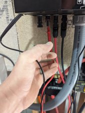
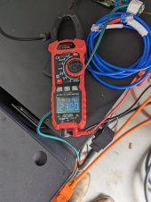
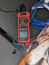
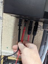
Well I just went out an measured my PV inputs from my MPP 8048 MAX units and its not good.

PXL_20230220_154052984.jpgPXL_20230220_154047446.jpg

PXL_20230220_154020002.jpgPXL_20230220_154023002.jpg

PXL_20230220_154024916.jpg
 
This thread has additional info on this topic.


Beside items described in above thread, there are a couple of other things that can cause leakage to ground.

Your PV panels can develop leakage resistance path from flat wire PV cell interconnecting strips within panel and the PV panel frame due to humidity intrusion near the edges of front glass to backing plastic lamination seal. You can check this on each panel with an ohm meter from each panel power lead and frame of PV panel. Should have greater than 200K ohms of resistance.

EMI filters on AC input and AC output of inverter have small capacitors that are connected to inverter case that can leak 5 to 10 mA of AC current to inverter metal case. This can cause issues to upstream GFCI breakers like in an RV park shore power outlet.

When Will blew the DVM 10 amp fuse, that is due to the lack of isolation between PV input and AC output of inverter and is described in above thread link.

If you accidentally or intentionally ground the PV- or PV+ inputs while inverter AC output is active you can blow out the HF AIO inverter's sinewave PWM IGBT H-bridge devices.

PV panel frame edge leakage described above can screw up AIO inverter's SCC MPPT controller. This can range from just non-optimum MPPT point resulting is less PV power yield to damaging SCC MPPT controller or inverter if leakage is bad enough.

All this is similar to the 50's and 60's days of transformer-less radios and TV's. After the plastic knob broke off you had a good chance of getting shocked by attempting to adjust the brass shaft. This gave way to the polarized AC cords where the wider flat prong of AC plug was always neutral of AC.
 
Last edited:
This thread has additional info on this topic.


Beside items described in above thread, there are a couple of other things that can cause leakage to ground. Your PV panels can develop leakage resistance path from flat wire PV cell interconnecting strips within panel and the PV panel frame due to humidity intrusion near the edges of front glass to backing plastic lamination seal. You can check this on each panel with an ohm meter from each panel power lead and frame of PV panel. Should have greater than 200k of resistance. EMI filters on AC input and AC output of inverter have small capacitors that are connected to inverter case that can leak 5 to 10 mA of AC current to inverter metal case. This can cause issues to upstream GFCI breakers like in an RV park shore power outlet.

When Will blew the DVM 10 amp fuse, that is due to the lack of isolation between PV input and AC output of inverter and is described in above thread link.

If you accidentally or intentionally ground the PV- or PV+ inputs while inverter AC output is active you can blow out the inverter's sinewave PWM IGBT H-bridge devices.

PV panel frame edge leakage described above can screw up AIO inverter's SCC MPPT controller. This can range from just non-optimum MPPT point resulting is less PV power yield to damaging SCC MPPT controller or inverter if leakage is bad enough.
Thanks for the link. I gave that thread a quick once over - and the only question I am left with is - Is this unsafe? Is someone going to get killed from a panel malfunction in normal operation. Obviously in maintenance, you turn off EVERYTHING.. or take the risk of the kills.

My concern is a malfunction at the panel where someone may touch the frame while the inverter is on - not knowing something is busted and gets the shock of their life? Are there any mitigation strategies if the answer is yes?
You always should have every metal electrical box grounded to common single point main panel ground. This includes breaker panels, inverters, subpanels, generator port box, and DC breakers metal box.

Dealing with PV connections is considered the same as working with AC connections within breaker panel. You have to know what you are doing. HV DC PV arrays are worse than 240/120vac breaker panel connections.

The floating PV inputs on HF AIO inverters is why you must use double pole breakers on PV+ and PV- connections so when you shut breaker off all power from inverter is isolated from PV panels.

You still have to be careful of HV DC created by a PV array. You cannot turn the sun on and off.
PV arc 600v array.jpg
 
Last edited:
Proper grounding of everything makes sense, I don't know why someone would do otherwise. Aside from grounding and NOT bonding PV - to ground, the failure modes are safe with these units is what I am gathering. If everything is grounded properly, the current will return to ground via the fast path instead of through a human. Got it. Anything else I should worry about?
 
I have a similar situation with the system on my boat. When my inverter is turned on I am seeing anywhere from 60-150 VAC and 50 to 200 ma when connecting my meter between the frame of my hard top and a known ground. When the inverter is off but the panels are charging the batteries all is good, so I can only summise that the inverter is "back feeding" AC current somehow , but I checked resistance between my DC solar wires and the panels and frame and I have zero conductivity..... incidentaly the frame is NOT grounded and I'm reluctant to do so it until I can figure this out as I fear more problems from stray current corrosion. Any pointers would be appreciated. Incidentally my inverter is a Sungold power 6548, with 48v 100AH rack style batteries.
 
Back
Top