diy solar

diy solar

Need some help with my travel trailer solar system .

Eskapet

New Member
Joined
Apr 21, 2024
Messages
6
Location
Canada
Hi Everyone
I bought a half built travel pod trailer and I am finishing /upgrading the solar system and I was wondering if anyone would have a chance to look at a rough wiring diagram I’ve done and confirm what I am doing is okay and answer some of my questions.
As it is now there are 2 100w Renogy panels and a 20amp charge controller . Panels are connected in series but I am going to change them to be in parallel (as suggested by BLUETTI ) .
I just bought blietti eb70s portable power station and a bluetti 200w portable solar panel .
The trailer has a fuse box wired with individual fuses to power A small pump ( max 7.5 amp) , a small fridge ( max 6 amp) and some lights,fans and usb outlets.
I plan to mainly power the fridge independently of the trailer system with the bluetti power station but I want to option to be able to power it with the trailer system too .


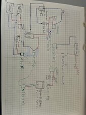
The plan is to have it so I can switch between the existing 12v car battery and the bluetti power station to power the trailer system and so I can charge the bluetti or the car battery with the trailers solar panels .
I am thinking to do this by using xt60 plugs so I can easily switch between the two batteries.
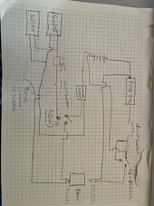
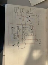
I have done a wiring diagram of what I plan to do but the main things I’m not sure about are :
- I am going to have circuit breakers but i am not sure on the exact type and location . BLUETTI suggested using a15 amp breaker before going into the fuse box and coming from the solar ( as I’ve drawn in the diagram ) but would I need a 20 amp breaker for the battery system as the charge controller is 20 amps ?
Also is a single pole breaker okay ?
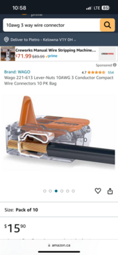
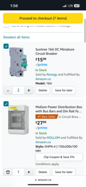
I was planning on getting the breakers in the photo attached but they only come in 16 and 32 so would need to get a different type if I use the 20 amp

- would I still need inline fuses on the output cables going from the bluetti and the battery ( see the diagram where I have drawn fuses with a question mark ?)
- Renogy suggest using their 20amp anl fuse between the battery and charge controller , would a standard blade inline fuse be okay here ?


Thanks so much for any help or advice it’s very much appreciated.
 

Attachments

  • IMG_0271.jpeg
    IMG_0271.jpeg
    167.3 KB · Views: 16
  • IMG_0272.png
    IMG_0272.png
    229.3 KB · Views: 9
Last edited:
Moving power between the tow vehicle and the trailer in significant amounts of low voltage DC can be tricky.

One of the better ways to do it IMHO is to buy mid size inverter and feed it from the starter battery of your tow vehicle.

Run 120 vac from the vehicle to the trailer and just charge the battery pack that way.

As far as solar powering your fridge in the trailer - just move up to 400 watts now, as 200 watts is really just a trickle charger. 400 watts is when it is enough to really be viable and reliable.
 
When you say existing car battery, you mean the trailer's battery and not your actual vehicle cranking battery?
and by car battery I assume means a lead acid battery? hopefully a deep cycle batt, or at least a marine battery.

It will be more difficult to charge two types of battery off one solar system. You would really need two solar systems working off one set of panels, or have a charger that automatically sees that you changed battery types mid-day.

If you get excited about using portable panels and setting them up and baby sitting them while camping then all the better. Otherwise I would just add another 200 watts if it will fit on the roof, or a 100, and dedicate one set to buletti and one to car battery (rv battery?), The fridge might need more power so give it the 200 watts of solar and the rv battery can be fine on 100 watts assuming you do not use much power off it.
Get fancy and have a way to move the 100 watts solar for car batt over to the fridge bluetti battery just in case you need more solar charging.

You fridge is 12 volt DC?

You do not need a fuse on both the negative and positive sides, just on the positive. Don't use a "fuse". Use circuit breakers. Use DC circuit breakers, not house AC breakers. Get the amperage rating a little above what will be running through it - should be based on what the wires can handle, but if wires can handle way more than what you run, the err on the side of what you run so breaker trips more easily when the re is a short. You do not want a 100 amp DC breaker for a 5 amp load run. The breakers will also give you an on/off switch option as you can just flip the breaker on or off. Disconnect the solar positive feed first before disconnecting the plugs or the battery - this is for the charge controller usually unless it specifically says that this is not necessary.
Thanks so much for your reply ,
Sorry for the confusion , it’s just a marine battery, we are not wanting to charge the trailer system via the car .

The plan was to just switch between charging /using the trailer marine battery and the bluetti manually ( if the trailer battery is getting low we can switch it so we are using the BLUETTI battery and charging the solar battery without using it and vise versa ). But mainly the BLUETTI will be charged via the portable solar panels and used to power the fridge independently of the trailer system . We may just want to charge the BLUETTI with the trailer roof solar system when we are driving when the roof panels will be in the sun if the BLUETTI is low . But the two batteries (bluetti and marine battery ) will never be charging at the same time via the roof system .
Fridge is 12v 6 amp
With the breakers, I was planning on getting 16 amp single pole miniature dc breakers ( see photo attached in original post ) . Is this okay ? I was basing it off the total output and off what the main wires that go from the fuse box to the battery can take . The wires going from the fuse to appliances are smaller but these are individually fused to suit the wire size . 15 amp is also what bluetti said I needed for their power station so I thought to just go with that for both .
And to confirm you are saying I don’t need any fuses if I use breakers ? Not even from the charge controller to the battery(As recommended in Renogy manual ) or should I put a breaker here too ? I was only planning on putting breaker on the input (from solar ) right before coming from the panels and in the output right before going to the fuse panel .

Thanks again !!!
 
If they say to use a fuse also then why not... Up to you.
I only use the breakers. Fuses date back to when electricity was first used, breakers are a more modern invention to replace the one-time-use fuses. 16 amps should be enough, you will know quick enough if you start tripping breakers all the time to get higher amp ones, but then you do not want to if the wires are only rated for 15 amps.
Those "battery cut-off" switches everyone uses, the big square box with round dial is what you need. It is more precisely an A-B-AB-Off switch where you can select completely off, or A side only, or B side only, or A and B side together. A being your bluetti, B your LA batts, and AB both (dont do both you said). OR OR you can reverse that and have two sources of charge (like solar and/or alternator) where A is alternator, B is solar, AB is both and Off cuts all charge power to one battery only. OR OR OR you could have two cut-off switches and have one control the dual charger side and one control the two battery side where the first switch on the charger side selects charging mode, and then sends electricity to the second switch which selects what battery(s) to send electricity to.
Thanks again for your help.
The 1/2/off switches sound great .
Do you mind having a look at the new wiring diagram I’ve done(see the image attached ) and let me know if what I’m planning to do looks right ?
I’m thinking to have two of those switches , one for the solar input (so I can change between charging the bluetti and the marine bat) and then for the output ( so I can change between powering the trailer with the bluetti or marine bat )
.
my main question is for the negative wire coming from the solar .. is it fine to just do a tee connection to this wire so one wire can go to the bluetti and one to the charge controller? . I was thing to just get one of those 3 way wire connectors (see image ) or I could solder it .
Thanks
 

Attachments

  • IMG_0319.png
    IMG_0319.png
    271.9 KB · Views: 3
  • IMG_0318.jpeg
    IMG_0318.jpeg
    164.2 KB · Views: 3
Moving power between the tow vehicle and the trailer in significant amounts of low voltage DC can be tricky.

One of the better ways to do it IMHO is to buy mid size inverter and feed it from the starter battery of your tow vehicle.

Run 120 vac from the vehicle to the trailer and just charge the battery pack that way.

As far as solar powering your fridge in the trailer - just move up to 400 watts now, as 200 watts is really just a trickle charger. 400 watts is when it is enough to really be viable and reliable.
Thanks for your response!
Sorry for the confusion but I’m not charging from the car .
 
Instead of lever nuts I would go lugs, copper lugs.
Screen Shot 2024-04-26 at 8.59.08 PM.png
Do not solder them, use a crimper or a hammer and a flat head screw driver. Put the cable in, pound with hammer some, use flathead to hammer a slot divit (do not cut) longways in the crimp. The idea is squeeze and make as much copper to copper contact between the wire and the lug as possible. They make a special crimper tool for big lugs but a hammer method works too.
You can find lugs cheap somewhere I am told. I have copper pipe and make my own (is quicker than a store run).

Im not sure in your drawing, between charge controller and fuse box, is that the battery symbol? It must be.
Red is positive, black negative... I think I understand it and it looks right. The fuse box is effectively your RV.

Yes, you can combine the negatives from all and both batteries, they will be connected anyway electrically being grounded to the chassis.
Neg is only important to a shunt, which you do not have.

If you use a shunt, your negative from battery to the shunt cannot be interrupted. All neg power flows off the shunt, only the shunt flows off the neg battery terminal, so the shunt becomes effectively your neg battery terminal. you do not show a shunt, so no worries there.
bluetti will monitor itself and your can use voltage on a FLA, so dont bother with a shunt. This info just for a future lurker reading...

Shunts are great for lithium batts tho.
 
Instead of lever nuts I would go lugs, copper lugs.
View attachment 211709
Do not solder them, use a crimper or a hammer and a flat head screw driver. Put the cable in, pound with hammer some, use flathead to hammer a slot divit (do not cut) longways in the crimp. The idea is squeeze and make as much copper to copper contact between the wire and the lug as possible. They make a special crimper tool for big lugs but a hammer method works too.
You can find lugs cheap somewhere I am told. I have copper pipe and make my own (is quicker than a store run).

Im not sure in your drawing, between charge controller and fuse box, is that the battery symbol? It must be.
Red is positive, black negative... I think I understand it and it looks right. The fuse box is effectively your RV.

Yes, you can combine the negatives from all and both batteries, they will be connected anyway electrically being grounded to the chassis.
Neg is only important to a shunt, which you do not have.

If you use a shunt, your negative from battery to the shunt cannot be interrupted. All neg power flows off the shunt, only the shunt flows off the neg battery terminal, so the shunt becomes effectively your neg battery terminal. you do not show a shunt, so no worries there.
bluetti will monitor itself and your can use voltage on a FLA, so dont bother with a shunt. This info just for a future lurker reading...

Shunts are great for lithium batts tho.
Yes that is the battery on the diagram . And yes red is positive and black is negative.
I actually am using a shunt, I just didn’t put that in the diagram as I thought I’d keep it simple .
So just to clarify , you are saying I can run all the positives from both batteries (via a bus bar ) ? And does that include the negative from the solar ?
I have done another diagram that shows all negatives running to a bar bus , I have also included the shunt on it . Do you mind confirming if that is what you meant and that will work . ? I have attached this diagram
Yeah I am using crimper plugs for everything and I have a crimping tool and a kit of all different plugs , i just wasn’t sure if my plugs would fit two wires to do a 3 way tee connection but if i can combine all negatives via a bus bar then I won’t have to worry about doing a 3 way splice anyway .

With the grounding , is just one ground wire from the bus bar to the chassis okay ? I don’t need to ground anywhere else do i?

I can’t thank you enough for all your help ! If this last iteration is correct I’ll be wiring this up early this week and it looks like such a better and more simple system than what I was originally planning with all the plugs ! Thanks again !!!
 

Attachments

  • IMG_0327.jpeg
    IMG_0327.jpeg
    146.9 KB · Views: 3
Last edited:
Looks right**edit...
Yes, for yours, run the solar neg to the bus bar.
Run the pos to the switch.
Run the switch to either the controller or bluetti.
From buss bar run to the shunt or straight to bluetti.
** I edit so it makes more sense....

Does your controller have a "light bulb" output? By that I mean output for accessories. This way you run your fuse box off the controller, not the battery - goes through your 1/2 switch. If so changes needed in your drawing to make fusebox pos & neg connect from the controller. The controller will be able to limit how deep the battery is discharged this way.
If you need to run a big item off the battery post then run that one item off the battery post, but otherwise the controller will provide a safeguard.BUT, if you do then that will be bypassing your 1/2 switch, so you either need another set of switches, or just be happy that one thing always and only runs off that one battery. I run my fridge off the battery post, but everything else off the controller. The fridge monitors low voltage also so has its own safeguard. (my system is two matched solar systems, each w panels, controllers and batts. One sys powers fridge and a nearby light and an unused Dc outlet, the other powers everything else).

Keep the cable length the same on positive and negative from the panels to the controller to the batteries.
You can ground the battery neg terminal to the frame, err, actually, ground the shunt instead so no neg voltage skips the shunt. You should ground your fuse box to the frame too. No other grounding needed between the solar/battery and the fuse box. After the fuse box you can do weird stuff without affecting the ideal charging environment.

I use this, because my batteries match, but you do not ever need to combine both your batteries since they do not match.
https://www.ebay.com/itm/402334270145 it lets me do 1-or-2 or 1-and-2 or off. You just need to do 1 or 2 or off.
AB.png

I dont remember what controller you have and not familiar with it anyway, so go by what they say.

I have used both these style breakers with no issues.
Screen Shot 2024-04-27 at 9.10.17 PM.pngScreen Shot 2024-04-27 at 9.09.25 PM.png
These can be screwed straight to the wall, no breaker box needed. I use them for on/off switches, not to protect the wires, but a short will trip them just the same. They make lower than 30amp, these just quick pics I copied....
The one on the left has rubber caps that cover the pos nuts, and can pop off and can short out if something bumps it. You need ring terminals on the cable.
The one on right is completely sealed so cannot short on anything ever unless it physically breaks, so I have been using them lately. You just shove a bare wire in and tighten the lock screw, so easier to use. They seem more cheapo than the left one, but have been good so far.
 
Last edited:
Looks right except for the neg buss bar. Someone else chime in if Im wrong. Run the solar panel straight to the controller, do not share a ground yet. From the controller run the neg and pos straight to the FLA battery (shunt discussed already).
Run solar straight to the bluetti (it has its own controller and shunt).
Use the selector knob as discussed already to switch sources/destinations.
The controller will be grounded, thus the solar panels will have ground through the controller too - is grounded by virtue it is both connected to battery neg which is grounded to frame, and also grounded (via neg cable) to the fuse box which also grounded to frame.

Does your controller have a "light bulb" output? By that I mean output for accessories. This way you run your fuse box off the controller, not the battery - goes through your 1/2 switch. If so changes needed in your drawing to make fusebox pos & neg connect from the controller. The controller will be able to limit how deep the battery is discharged this way.
If you need to run a big item off the battery post then run that one item off the battery post, but otherwise the controller will provide a safeguard.BUT, if you do then that will be bypassing your 1/2 switch, so you either need another set of switches, or just be happy that one thing always and only runs off that one battery. I run my fridge off the battery post, but everything else off the controller. The fridge monitors low voltage also so has its own safeguard. (my system is two matched solar systems, each w panels, controllers and batts. One sys powers fridge and a nearby light and an unused Dc outlet, the other powers everything else).

Keep the cable length the same on positive and negative from the panels to the controller to the batteries.
You can ground the battery neg terminal to the frame, err, actually, ground the shunt instead so no neg voltage skips the shunt. You should ground your fuse box to the frame too. No other grounding needed between the solar/battery and the fuse box. After the fuse box you can do weird stuff without affecting the ideal charging environment.

I use this, because my batteries match, but you do not ever need to combine both your batteries since they do not match.
https://www.ebay.com/itm/402334270145 it lets me do 1-or-2 or 1-and-2 or off. You just need to do 1 or 2 or off.
View attachment 211915

I dont remember what controller you have and not familiar with it anyway, so go by what they say.

I have used both these style breakers with no issues.
View attachment 211916View attachment 211917
These can be screwed straight to the wall, no breaker box needed. I use them for on/off switches, not to protect the wires, but a short will trip them just the same. They make lower than 30amp, these just quick pics I copied....
The one on the left has rubber caps that cover the pos nuts, and can pop off and can short out if something bumps it. You need ring terminals on the cable.
The one on right is completely sealed so cannot short on anything ever unless it physically breaks, so I have been using them lately. You just shove a bare wire in and tighten the lock screw, so easier to use. They seem more cheapo than the left one, but have been good so far.
okay so I just run the solar direct to the controller but for the negative I would have one wire splitting into two and one going to the controller and one to the power station . Is that right ?

When you ask about the lightbulb outlet on the controller , you mean the charge controller for the solar panels not the bluetti power station don’t you ?
My charge controller had positive and negative ports for ; battery , pv and load .
I think load is what you are talking about ?
But from what I’ve read online the load is only powered when the solar is getting sun so if I ran that into the fuse box we would only have power during the day ? Is this what you mean ?
I think I may be misinterpreting you ?
Btw just so you know I will mainly be charging the fridge with the bluetti separate from this system and the car battery and solar of the trailer will be to power lights and pump and charge phones (usb plug inside trailer ) I just wanted the option to be able to plug the fridge into this system if the bluetti was running low and vise versa I wanted the option to be able to power this system via the bluetti if the marine battery is running low .

With the switches that was what I was planning to get the 1-2off ones and the breakers I’ve already ordered two breakers and a breaker box .


Thanks again !
IMG_0272.png
 
I edited previous post:
run the solar neg to the bus bar.
Run the pos to the switch.
Run the switch to either the controller or bluetti.
From buss bar run to the shunt or straight to bluetti.

The only danger I see you making is not wiring the shunt right and losing information, but no damage comes of this.

Load, yes, same as my light bulb icon. My Load from the controller runs off of the battery (or solar panels... one in the same). Your controller should take power from the battery as well, would not make sense for it not to be able to run off the battery, so I think it must. I bet you read false info.

Sounds like you're doing the same thing, using one batt for fridge and the other for everything else, and the other battery as backup for the fridge if needed. When boondocking the fridge is king and, like the King in chess, has to be protected at all cost.

I suggest splitting your roof solar into two systems so each battery at least always has some charge. Going to be a pain everyday to have to switch things half way through the solar sun cycle, or maybe it works out you can alternate days. Make a switch so you can put all solar into one battery if needed. IDK the best way, you can do with switches, or maybe, maybe you can just split the solar pos to run to each battery (one controller and one bluetti), but IDK how this works in the real world or if somehow one battery can suck power off the other this way.

I looked at mine. Yes, I am connected through a bus bar in the fuse box on the neg side for two charge controllers. The neg cables in question are actually touching, not that it matters, and I kept the length of neg cable the same as the length of the pos for each set.

Mine actually has a 3rd solar system that is switched, so I mis spoke about switching... gets complicated, but I have a deployable set, so one set is in the shade (under the other panel) until I park and deploy the 3rd set. So I select for the 3rd set to charge the battery who's panels are shaded by the deployable set, and when that is deployed and all the panels are in the sun, then I can select which battery gets the 3rd bonus set of panels/controller. 200 watts times 3, for 600 watts total. Plenty for me. I only deploy when needed. Because I have an extra controller that makes my situation more simple as I only need select where that power goes.
Interesting that the fridge battery last longer than the everything else battery.
 
Last edited:
Back
Top