100kwh-hunter
New Member
- Joined
- Nov 29, 2020
- Messages
- 130
Having 3 * (16*280Ah) give me 7.7 kwh....in a field test.....7.7kwh....!
Wait what...3*16 cells*280ah...must be (48v*280ah=13,4kwh per 16 cells, each)..........times 3....40kwh? minimum
So 48 cells must give me ~40-45 kwh????
Three batterys of 48v 280Ah each.....
According to my calculations i must have a minimum of 35kwh?
My setting on my bmses (daly btw)
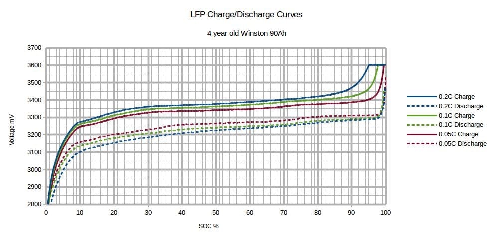
low v protect per cell: 3.000v
high v protect per cel: 3.300v
low total v: 48v
high total v: 53,6v
This is according? 80%DOD????So 6000 cycles aka 10 years of use?
80%dod would be a 230ah on 48v aka 8kwh?....per battery...and not 2.5kwh per battery
Question numb one; what means and what is basically DOD?
Number two; did i get my setting right?
My new settings:
low v protect per cell: 2.8v
high v protect per cell: 3.37
low total: 45v
high total: 54V
But com on....11.000 euro of cells..just 7.7 kwh....With the old settings? on 80%DOD
Did they dupe me?
Or where my settings wrong?
Daly is really a junkyard dog btw, dont fuck one inch or 2.5cm or ill bite....
Question numb one; what means and what is basically DOD?
Number two; did i get my setting right?
With best regards Igor
Wait what...3*16 cells*280ah...must be (48v*280ah=13,4kwh per 16 cells, each)..........times 3....40kwh? minimum
So 48 cells must give me ~40-45 kwh????
Three batterys of 48v 280Ah each.....
According to my calculations i must have a minimum of 35kwh?
My setting on my bmses (daly btw)
low v protect per cell: 3.000v
high v protect per cel: 3.300v
low total v: 48v
high total v: 53,6v
This is according? 80%DOD????So 6000 cycles aka 10 years of use?
80%dod would be a 230ah on 48v aka 8kwh?....per battery...and not 2.5kwh per battery
Question numb one; what means and what is basically DOD?
Number two; did i get my setting right?
My new settings:
low v protect per cell: 2.8v
high v protect per cell: 3.37
low total: 45v
high total: 54V
But com on....11.000 euro of cells..just 7.7 kwh....With the old settings? on 80%DOD
Did they dupe me?
Or where my settings wrong?
Daly is really a junkyard dog btw, dont fuck one inch or 2.5cm or ill bite....
Question numb one; what means and what is basically DOD?
Number two; did i get my setting right?
With best regards Igor