diy solar

diy solar

Off grid balancing using bulb to drain runner cell

Jesshaines

New Member
Joined
Mar 29, 2022
Messages
36
I'm trying to manage an out of balance pack. While living off grid.

I've come across a couple suggestions here and on the off-grid garage YouTube channel of basically using a light bulb to drain a single cell that's running.

Sorry, total noob! Can someone give a few more details of how actually to do this?

One person suggested a car headlight bulb. Does it matter that my cells are 3.2 volt nominal? Won't the headlight bulb be calibrated to run off 12 volts? Or maybe it will just shine dimly with the lower power supply....?


Also, do I need to worry about polarity of bulb matching cell when using this method?

Any help input suggestions welcome. Thank you
 
An incandescent light bulb is just a resistor, only it gives off both light and heat, not just heat. You can put any voltage to them and they'll take it, however if you put too high a voltage they will overheat. (You have the opposite problem)
Headlight bulbs may not be simple resistors though, they can be all sorts of technology.
How much power do you need to drain from your cell to get it down to where the others are? Specifically, how many Ah is the cell and how many volts high is it?
 
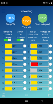
BMS image attached...

Simple answer is, not sure...

Longer answer is -

Basically I started at my system about a week ago. Cell number 8 was starting to run at about 70 to 75% state of charge. I've been managing by simply turning off the breaker to my panels when I need to be away all day and can't monitor the system.

I have a heltech active balancer I haven't connected yet as I've been researching and learning how that works.

The system was at about 60% state of charge when I left yesterday and I chose to leave the panels off, partly as an experiment. They've mostly had around 001 volts deviation at that state of charge.

I came home to higher deviation, around .03 volts which I didn't expect and 55% state of charge.


I'll be home for a little bit today and can have the panels on and see how the system behaves. I'm expecting that cell 8 to keep running.

As I'm off grid and really don't want to disassemble my battery and pack it up to a friend's house for top balance, trying to figure out if there are intermediate steps I can take.


I think maybe this combination of draining runner cells and using the active balancer when all cell voltages get over 3.4 seems like it's worth a shot anyway.
 

Attachments

  • Screenshot_20221026-073826.png
    Screenshot_20221026-073826.png
    355.3 KB · Views: 8
An incandescent light bulb is just a resistor, only it gives off both light and heat, not just heat. You can put any voltage to them and they'll take it, however if you put too high a voltage they will overheat. (You have the opposite problem)
Headlight bulbs may not be simple resistors though, they can be all sorts of technology.
How much power do you need to drain from your cell to get it down to where the others are? Specifically, how many Ah is the cell and how many volts high is it?
And thank you! That makes sense...

I was thinking probably an older light bulb for an older model vehicle, not something new and fancy would be a place to start
 
And thank you! That makes sense...

I was thinking probably an older light bulb for an older model vehicle, not something new and fancy would be a place to start
I've seen on off-grid garage channel he has a board of four bulbs. But I think the advantage with the car headlight is it has easily accessible terminals. That's my thinking anyway but if you have suggestions of other resistors that would work, I'm all ears
 
I have a heltech active balancer I haven't connected yet as I've been researching and learning how that works.
This is the real solution. Wire this up and allow it to bleed off the high one for you. I'll go a bit deeper below but this is the actual path you should take.
Otherwise you can put any resistor across battery 8 to burn off the excess .025 volts. Say for example that I had a 1/4w 100ohm resistor (the sort of thing many of us have lying around all over the place).

You don't want to burn off more than a 1/4 of a watt of power or it'll overheat these common 1/4 watt resistors.
Power is V*I but you need to solve for I first. I is V/R so with a 100ohm resistor you'd be pulling 3.285V/100ohms or 0.03285 Amps. The power would be 0.10791225 watts which is below the 1/4 watt threshold you're looking for.
The amount of time it would take to burn off .025 volts depends on the Ah of your system but you can just monitor it and yank it when it's happy.
If you have any other resistors lying around you'll find that the math above can accomodate for any resistance.

But--- You already have a device that does this for you automatically, I think you should use it instead.
 
Worrying about the voltage when your not fully charged/discharged can put you on a wild goose chase.

The correct way is to have a BMS that shuts off the charge and/or load when the cells get to high or too low. When the bms turns off the Hiltec active cell balancer should can still balance and correct the charge state of that cell. If you want to bring the high cell down quickly then you can use the light bulb method. But you could also have low cells that can be a problem.
 
Say for example that I had a 1/4w 100ohm resistor (the sort of thing many of us have lying around all over the place
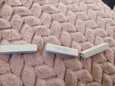
I've got ten of these lying around lol....I'm not super excited about stringing ten of them in series though.

So current will flow with just this simple circuit on the battery posts?

I come from an automotive background and unfortunately electrical teacher sucked! LOL. I seem to remember something about without a load, the current won't flow. But I guess in this case as long as the circuit is complete, the resistors are the load?

Sorry if this is kindergarten electrical. Just trying to make sure I understand the principles.

Thanks for the input about the active balancer. I have a friend who has essentially the same equipment I do and I think the problem is for some reason, either the charge controller or the BMS aren't shutting off when single cells go over voltage. She's been doing basically the same thing I have, managing her system so it doesn't overcharge by turning her panels off/on day by day based on the state of charge. Not an ideal system!

Thank you again.
 

Attachments

  • IMG_20221026_082450.jpg
    IMG_20221026_082450.jpg
    370.7 KB · Views: 3
I've got ten of these lying around lol....I'm not super excited about stringing ten of them in series though.

So current will flow with just this simple circuit on the battery posts?

I come from an automotive background and unfortunately electrical teacher sucked! LOL. I seem to remember something about without a load, the current won't flow. But I guess in this case as long as the circuit is complete, the resistors are the load?

Sorry if this is kindergarten electrical. Just trying to make sure I understand the principles.

Thanks for the input about the active balancer. I have a friend who has essentially the same equipment I do and I think the problem is for some reason, either the charge controller or the BMS aren't shutting off when single cells go over voltage. She's been doing basically the same thing I have, managing her system so it doesn't overcharge by turning her panels off/on day by day based on the state of charge. Not an ideal system!

Thank you again.
You will have to put them all(resistors you have) in parallel. At 3.2 volts and 100 ohm's you will only be pulling .032 watts which is way under the spec of them at .25 watts.

You can look in the settings in the BMS app to tell at what point the BMS will shutdown....the highest one is labeled red in your app and and lowest is gray....that doesn't really mean there is a problem being red.
 
Worrying about the voltage when your not fully charged/discharged can put you on a wild goose chase.
?
The correct way is to have a BMS that shuts off the charge and/or load when the cells get to high or too low. When the bms turns off the Hiltec active cell balancer should can still balance and correct the charge state of that cell. If you want to bring the high cell down
Ok so I think my real problem is whatever's going on with the equipment the BMS isn't shutting off charge when single cell goes over voltage. I haven't had that problem yet with my individual system, but my friend with identical equipment has.


My SCC is a brand Powmr... It's advertised as 48 volt compatible, but it s settings are only an average of the pack (actually pack/4, so in the 11-14v range). It doesn't have absorption/float settings for individual cell voltages.

So it seems like the problem may be that my pack needs to be well balanced for the SCC to do its job as well....?
The SCC cant help individual cell voltages...that is the job of the BMS and Active Cell Balancer. The balancer will take energy from the high cell and send it to the low cell and keep doing that very slowly till they are even. Cells are only damaged if they go above 3.6 volts or under like 2.5 so if they aren't over those highs and lows then there is nothing to worry about, if they do go over or under those values the BMS should shut down the energy flow.

You should let your system fully charge periodically to get a true good balance.
 
Cells are only damaged if they go above 3.6 volts or under like 2.5 so if they aren't over those highs and lows then there is nothing to worry about, if they do go over or under those values the BMS should shut down the energy flow.

You should let your system fully charge periodically to get a true good balance.
? Thank you
 
Your 10 ohm resistors are built to dissipate a lot of heat (10w each).

If you used one of those instead of the theoretical 100w resistor you end up with the following math:

I is V/R so with a 10ohm resistor you'd be pulling 3.285V/10ohms or 0.3285 Amps.
Power is V*I which is 1.0791225 Watts. (Well below the 10 watts your single resistor can dissipate).

You can certainly use one of those 10W resistors if you like. It'll drain the power as desired if you want to play in this space.
Thank you!!!!

Seeing multiple examples of how the math works helps me trust I'm doing it right :) I really appreciate your help.
 
You will have to put them all(resistors you have) in parallel.
Careful- you meant to say series. In parallel it would pull a massive amount of power due to the super low resistance. Could get dangerous. ?
 
Careful- you meant to say series. In parallel it would pull a massive amount of power due to the super low resistance. Could get dangerous. ?
10 times 0.32 amps is 3.2 amps....10 times 1 watt is 10 watts.....hmmm.....lol....he has ten resistors....also he originally said they were 100 ohm.
 
Keep in mind, at 3.2x volts, a cell has MASSIVE amperage to resist change.
It would be better to let the cells reach 3.35x volts before trying to balance them.
Much higher in the knee.
 
Back
Top