diy solar

diy solar

Off grid dump load diverter idea?

ApproximatelySean

New Member
Joined
Jan 21, 2021
Messages
30
Ok so an idea for a dump load diverter, i think this should be easy enough with minimal programing..

Use the built in victron mppt dump load feature to switch on a relay when battery is 95-100% the realy feeds a second SSR controled by and arduino, the arduino reads from a small 10w mono crystilne referance panle mounted next to my areay, and PWM writes 10% lower than the read value to the SSR powering the dumpload, however im not sure what metric to measure with the arduino? voltage? attach the panel to a heater and mesure current? im sure theres better ways to do this but i can wrap my head around this.. any input appreciated (y)
 
To get a power reading from the small panel I would get a power resistor that can dump 10-20W of heat, measure the voltage drop across the resistor and you should get a half sensible reading. this won't directly relate to your main solar panels though as they are operating under mppt conditions and therefore will have a different relationship between solar radiation and power.

I think you are going to get problems with the victron MPPT running in absorption/ float mode so not extracting much power from the panels and waiting for your dump load to discharge the batteries enough to trigger it back into bulk. this means your batteries will be oscillated at 100% which might shorten their life. To avoid this, use a load which draws enough current to drop the battery voltage notably which should wake the controller

I would also lean towards using two CT clamps one on the controller output to the battery and one on the output to your load, then use the PID arduino library to control the difference to 0. this would get around wonky relationship between mini panel and main array. the 10W panel would still be a good idea to detect if there is actually a useable amount of sun.
Psudo Code:
WHILE (PowerResitorVoltage > Threshold && MPPTDumpLoadTriggered) do:
Turn on load (SSRPWM = 100%) *alternative
Delay 15 seconds
Start controlling the SSRPWM to make the difference between CT1 and CT2 zero
PID( input= CT1 - CT2, Output= SSR PWM, setpoint = 0 )

Something like that. it should turn off automatically by the victron MPPT

This might seem overly complicated but i find when you add the nuance to make these things work they are. Devils in the detail

*alternative: here you could do PowerResitorVoltage x Calibration value. For example if your heater is 1000W and your 10W panel reads 2.5V when when your main array puts out 500W then you can solve for PWM x HeaterPower = VR X calValue So 0.5 x 1000 = 2.5 x CalFactor

If you have not used a PID before i would very much recommend them, very cool tool in engineering. not as complicated as they might seem, watch a couple of videos, all you have to do is point it in the right direction and do some subjective tuning
 
What are you dumping from, panels or battery? What are you dumping to? I monitor panel voltage and start dumping from array when voltage goes over expected power point. You can't tell that much from battery voltage. A pilot panel can give additional information.
 
This is an old post. The OP may have aged out of service.
ahh, I didn't check the date xD I had been looking into something similar so got hooked in quick

What are you dumping from, panels or battery? What are you dumping to? I monitor panel voltage and start dumping from array when voltage goes over expected power point. You can't tell that much from battery voltage. A pilot panel can give additional information.
That is an interesting idea. I like it, that way you know there is sun and that the MPPT is not making full use of it in one measurement.

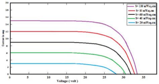
How do you adjust the the expected MPP voltage?
1709628052139.png
Image stolen from:
Performance Investigation of Grid Connected Photovoltaic System Modelling Based on MATLAB Simulation
Adnan Hussein Ali, Hassan Salman Hamad Al-Jewary, Ali Abdulwahhab Abdulrazzaq

you would have to know the relationship between MPP voltage and irradiance? do you study the relationship between output from the pilot panel and array MPP voltage over time to build up a picture, fit a line to the data points and use it to know what voltage to expect?

Sorry, should probably let this thread die, posting purely for my own interest
 
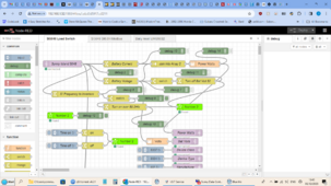
This is my method, needs the battery inverter to control the PV inverters via frequency shifting to work. Runs on a Pi running Node-red, the dump load is whatever is plugged into the Wifi switch which handles up to 13A at 230V. You could add extra wifi switches to have a cascade effect by adding on extra loads as the frequency increases over the 50.2 I have set for the first dump load.
 

Attachments

  • Screenshot (9).png
    Screenshot (9).png
    365.5 KB · Views: 7
Thats cool, so your house is islanded with frequency shifting compatible string inverters on the grid forming inverter. and if your Pi detects the sunny island increasing frequency and therefore ramping down solar production it turns on more loads. A neat solution if you have the right setup.

The OP wanted an adjustable load he could ramp up to use only the excess power which is something I have often wanted.
I guess you could combine our ideas and use a PWM/ Triac heater on the AC controlled by a PID which tries to keep the frequency at say 50.3Hz

Most set ups unfortunately don't have frequency coupled inverters though
 
Once I get around to it, which may be a long time as the current setup for all its crudeness of turning on a single fixed load is proving effective, then next step to to add a variable load based on this.


Code

 
Last edited:
Back
Top