diy solar

diy solar

parallel battery bank question

vulcan66

New Member
Joined
Oct 30, 2022
Messages
13
I'm wanting to put two 12v 100ah lithium batteries in parallel with a 1500 watt inverter on a travel trailer.

I'm just reading that some folks say to fuse each positive from the two batteries and others say just one fuse for max inverter draw. I'm also using a busbar and disconnect switch. Just having a little uncertainty about the fusing options here and best practices. My two batteries will be 100ah and some say 100 amp fuse on each positive and others say 150 amp on each positive due to the surge allowed on each 100ah battery. My previous smaller setup, with only one battery had just the one fuse between the inverter and the battery and of course appropriate fusing on the SSC and a properly sized solar disconnect/breaker.

These T-class fuses that are recommended are not cheap, but I'm happy to spend the $ for whatever offers the better protection. I do have some understanding of wire guage sizing and was plan on 2/0.

Appreciate the help
 
As mentioned one is fine. Only time we use at each battery is if the positive terminals are in a sketchy area (possibility of being shorted), in that case we use those marine type battery post fuses.
Could be what is confusing could not.
150ah might be a little close if the inverter has a high surge capacity. Just a little close.
Just remember the fuse is to protect the cable nothing else. With 2/0 you should be good for 200a for about 30 feet (from a weak memory).
 
Put a MRBF fuse rated 125amps on each positive post. If you get the fuse and holder from mouser you know it is real and it will be cheaper than amazon.

I looked these up the other day

https://www.mouser.com/ProductDetail/Bussmann-Eaton/CFCOVER-1R?qs=zijbFIqa2JEOjMDsOT7upA%3D%3D

https://www.mouser.com/ProductDetail/Bussmann-Eaton/CFBAR1-250SP?qs=r5DSvlrkXmKMfmwp3Zb/Bw==


Also fuse between the bus bar and the inverter.

If your cables to the bus bar are long consider fusing at the bus bar end as well. Not required with only 2 batteries but might save a problem in some corner cases.
 
Put a MRBF fuse rated 125amps on each positive post. If you get the fuse and holder from mouser you know it is real and it will be cheaper than amazon.

I looked these up the other day
https://www.mouser.com/ProductDetail/Bussmann-Eaton/CFCOVER-1R?qs=zijbFIqa2JEOjMDsOT7upA==
https://www.mouser.com/ProductDetail/Bussmann-Eaton/CFBAR1-250SP?qs=r5DSvlrkXmKMfmwp3Zb/Bw==


Also fuse between the bus bar and the inverter.

If your cables to the bus bar are long consider fusing at the bus bar end as well. Not required with only 2 batteries but might save a problem in some corner cases.
Thanks so much! This really helps. Forgot about Mouser. Purchased some components from them years ago. Nice to save a little $ in these times. Appreciate the help.
 
Put a MRBF fuse rated 125amps on each positive post. If you get the fuse and holder from mouser you know it is real and it will be cheaper than amazon.

I looked these up the other day
https://www.mouser.com/ProductDetail/Bussmann-Eaton/CFCOVER-1R?qs=zijbFIqa2JEOjMDsOT7upA==
https://www.mouser.com/ProductDetail/Bussmann-Eaton/CFBAR1-250SP?qs=r5DSvlrkXmKMfmwp3Zb/Bw==


Also fuse between the bus bar and the inverter.

If your cables to the bus bar are long consider fusing at the bus bar end as well. Not required with only 2 batteries but might save a problem in some corner cases.
So if fusing at busbar end too, similar size fuse to the inverter fuse?
 
So if fusing at busbar end too, similar size fuse to the inverter fuse?
Bus bar to inverter - use a class T and 250amp size. Make sure to get the right size mount for the fuse, in class T they change over at a certain number of amps as the package size is lengthened.

If you are talking about long cables between bus bar and battery the same MRBF fuses and sizes and holder.
So MRBF is not proper for bus to inverter or class T is just better? When you say 250 amp, I thought for the inverter the fusing would be 1500watts divided by 12 = 125amps X 1.25%=156 amp fuse. Is my math off for a 1500watt 12v inverter?
Thanks again for your help.
 
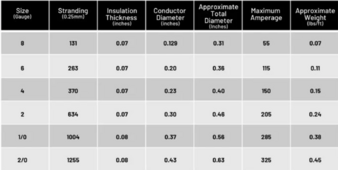
Sorry, I assumed you were using 2/0 welding wire - which is in the chart below and is good to 325 amps. You could go as small as 2awg wire for 205 amps and make the fuse 200 amps. If you are wondering this is from the windy nation website for welding wire. The NEC table for wire ampacity is based on THHN with a "Thermoplastic Insulation/Nylon Sheath" rated at 75c or 90c. The welding wire is a rubberiezed sheath that is rated at 105c. The other reason to use welding wire is flexibility.

table is below the picture of the wire as picture #3.


1714672194278.png


No, MRBF is great on batteries and to the bus bar, but between the inverter and the bus bar you want something with a higher AIC so it can interupt an arc better. (arc interupt capacity)

With larger 48v packs and more than 2 batteries in series you want class T per pack and if the battery doesn't have a protection device built in you want a MRBF or similar there.
 
Sorry, I assumed you were using 2/0 welding wire - which is in the chart below and is good to 325 amps. You could go as small as 2awg wire for 205 amps and make the fuse 200 amps. If you are wondering this is from the windy nation website for welding wire. The NEC table for wire ampacity is based on THHN with a "Thermoplastic Insulation/Nylon Sheath" rated at 75c or 90c. The welding wire is a rubberiezed sheath that is rated at 105c. The other reason to use welding wire is flexibility.

table is below the picture of the wire as picture #3.


View attachment 212892


No, MRBF is great on batteries and to the bus bar, but between the inverter and the bus bar you want something with a higher AIC so it can interupt an arc better. (arc interupt capacity)

With larger 48v packs and more than 2 batteries in series you want class T per pack and if the battery doesn't have a protection device built in you want a MRBF or similar there.
This is helpful information, really appreciate it. This is only my second small system and while I enjoy putting things together, I find electricity sort of like plumbing in the sense that one can become bewildered with all the various options and different paths to essentially achieve the same outcome. Hopefully I'm not the only one. Lol
I'm trying to improve my layout and organization this time, which is partly why a lot of questions. Since I'm going to have two busbars, pos/neg, can the T class fuse for the inverter connect directly to the busbar and cable lug to the other end of the fuse or does the T class style require it's own holder which would require other short jumpers between the fuse holder and the busbar? When I look at T class fuses online it seems they are intended to be used with their own holder. I thought if I was using an MRBF style, the holder could go right to the busbar and cable lug to other end. Please excuse my ignorance here, I have used MRBF style in the past, but outside of that just had exposure to blade type automotive and the little glass tube style fuses.
 
The Class T requires its own holder. You can't depend on it being structurally sound after it blows. In that case it would be a loose wire just flopping around.

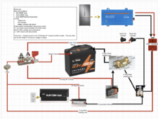
Download draw.io and make a good diagram of what you are doing. On windows 11 just hit 'prtscrn' button and capture an image of what you are putting in the circuit and then draw lines between to represent the wires. Here is my cpap backup as an example. Took about 10 minutes to make the basic diagram and a couple of hours until I had all the wires and lines exactly where I wanted them and labeled.

Note - in this case the inverter is only a temporary thing and only for a power outage. There is no class T because I am only using a single battery. The double MRBF is how I avoided the need for a bus bar.

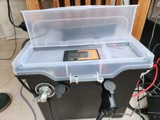
All of this fits inside a sewing case I got from the thriftshop for a couple of bucks. Well, the inverter is stored in a closet and the charger requires airflow so it is outside the box. Eventually I will add a MPPT and a couple of solar panels in place of the charger. I run the cpap off the 12v outlet.

cpap backup.pngIMG_20240308_130808.jpg
 
The Class T requires its own holder. You can't depend on it being structurally sound after it blows. In that case it would be a loose wire just flopping around.

Download draw.io and make a good diagram of what you are doing. On windows 11 just hit 'prtscrn' button and capture an image of what you are putting in the circuit and then draw lines between to represent the wires. Here is my cpap backup as an example. Took about 10 minutes to make the basic diagram and a couple of hours until I had all the wires and lines exactly where I wanted them and labeled.

Note - in this case the inverter is only a temporary thing and only for a power outage. There is no class T because I am only using a single battery. The double MRBF is how I avoided the need for a bus bar.

All of this fits inside a sewing case I got from the thriftshop for a couple of bucks. Well, the inverter is stored in a closet and the charger requires airflow so it is outside the box. Eventually I will add a MPPT and a couple of solar panels in place of the charger. I run the cpap off the 12v outlet.

View attachment 212934View attachment 212935
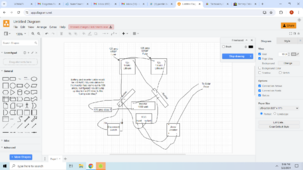
That looks like a great setup you have for your cpap. Nice and compact! I did try the drawing program and I'll get better at using it. It's a nifty tool. I've attached my drawing. On my first attempt I kind of mixed things up and actually laid it out so the bus was always hot and only the inverter was switched. I think I fixed that, but not sure on the negatives going directly to the bus. If both the + and - wires are the same length is it okay to do the negatives directly to the bus and the positives daisy chained together with a positive line coming down to the disconnect?Screenshot (1162).png
 
That looks like a great setup you have for your cpap. Nice and compact! I did try the drawing program and I'll get better at using it. It's a nifty tool. I've attached my drawing. On my first attempt I kind of mixed things up and actually laid it out so the bus was always hot and only the inverter was switched. I think I fixed that, but not sure on the negatives going directly to the bus. If both the + and - wires are the same length is it okay to do the negatives directly to the bus and the positives daisy chained together with a positive line coming down to the disconnect?View attachment 213017
I was thinking on the negative side I maybe need to do the negatives between the two batteries instead of direct to the busbar. I left out the battery shunt and was thinking the shunt needs one negative wire, coming from the battery before it hits the busbar. Another question is, I was trying to avoid stacking battery lugs. Is it okay to stack two lugs on top of the 125 amp MRBF Fuses?

Looks like my drawing needs to be reworked. Take two. ooops!

Use this verse stacking, and separate fuses. The problem with stacking on the MRBF is you can crack the fuse enclosure. The other and I think better option is to stack on the disconnect where you can torque properly and get the contact between lugs tight.

Make sure to use no-ox-id special on all contacts. It inhibits corrosion and the particles in it will cut through and oxidation already present.


You can use the 2/0 if you like, but the 2 awg is much more flexible. If you intend to upgrade the inverter at a later time then stick with 2/0.

Note - your wires from the positive poles of the batteries and negative poles need to have the same combined length.

i.e. if you have 3ft of cabling on battery A you should use 3ft on battery B. They don't have to be the same, but you want to present the exact same resistance to the charger so they stay balanced.
 
Last edited:
Back
Top