diy solar

diy solar

Parallel function of 2x50kW hybrid triple-phase Deye inverters without data comms

landau

New Member
Joined
Jun 1, 2024
Messages
6
Location
Croatia
Hello everyone,

After a couple of months of lurking on the forum I've finally decided to register and post a thread about my conventional/boring network engineering project that turned into a nightmare when it overlapped with solar technology. For context, I'm a research physicist who does R&D software engineering for a living and dabbles in all things computer related as a side hustle. In other words, I'm a complete amateur when it comes to deploying complex solar technology solutions.

A client hired me to deploy a computer network in his camp which containes a villa, 6 smaller houses, 3 larger ones, 4 outdoor pools, 10 jacuzzis etc. Everything was powered from the public power supply grid and a Deye 50kW hybrid triple-phase inverter coupled to batteries and PV panels. This year, the client decided that he will deploy another inverter, batteries and PV panels 250-300 meters away from the original. The fun began when they told me that I need to establish data comms between them.

I've tried every imaginable network topology and setup to connect them, CAT7 cables (provided by the client) daisy chained over network switches or range extenders, even a PTP wireless setup after I was told that a optical fiber/coax cable solution was unfeasible. No matter what I tried F29 fault kept popping up every single time the installer tried to connect them in parallel.

After painstaking troubleshooting they have let me off the hook - both Deye engineers and company that sold/deployed the second inverter concluded that data comms over that distance are not possible, BUT that it is possible that those two inverters work simultaneously on the same electric network with reduced efficiency. As I've said in the opening, I'm a lightyear away from being an expert in this field, but their statement sounded ludicrous from the get go.

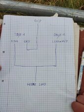
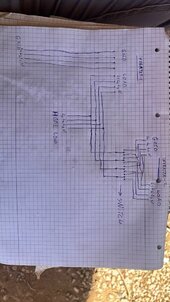
Their suggestion boils down to connecting the inverters through their load ports (rough electrical wiring diagrams are included). I fail to see how are they going to synchronize their phases in that configuration, (non-existent) data comms should do that. I've suggested that they simply separate the inverters and their panels/batteries/loads on respective subcircuits, but the client is extremely frustrated and he is rightfully demanding that the installers deliver what was promised, simultaneous function of 2 inverters on the same electric network.

My question is the following: is his request technically unfeasible and if it's not what are the avenues of approach to tackle this problem. Thanks in advance.
 

Attachments

  • IMG_20240531_125435.jpg
    IMG_20240531_125435.jpg
    166.1 KB · Views: 9
  • IMG-20240531-WA0010.jpg
    IMG-20240531-WA0010.jpg
    145.3 KB · Views: 9
Update: When the second inverter is shutdown and the first is connected to grid it's screen shows this (load supplying the grid, in other words complete nonsense). When both inverters are connected they show F18 AC overcurrent flow fault.
 

Attachments

  • IMG_20240602_112227.jpg
    IMG_20240602_112227.jpg
    88.1 KB · Views: 6
The data coms between the two inverters will be via CAN or RS485, it is not an Ethernet network and that's why it does not work and will never work.
Even with the correct data format that is one hell of a run, so I think the only practical way to set them up is as 2 entirely separate systems.
 
The data coms between the two inverters will be via CAN or RS485, it is not an Ethernet network and that's why it does not work and will never work.
Even with the correct data format that is one hell of a run, so I think the only practical way to set them up is as 2 entirely separate systems.
Thanks for the insight, now it makes sense why they don't have MAC/IP addresses. I was given a CAT7 cable and all that they said was that they need to be straight/not cross-over. They connected the inverters with a single CAT7 cable directly (which didn't work obviously) and then I used my computer network as a futile alternative. I've asked both Deye engineers and installers how could they communicate over that distance in the first place as CAT7 cables are graded at 100m. I didn't get a response to that question or my follow-up: what is the maximum allowed latency for parallel synchronization of inverters. Deyes manual doesn't mention parallel port cables at all, only pin-outs of the BMS, Meter, RS485, RS232 are shown.

I've suggested that they separate them entirely, but the deadline of the project doesn't allow for that. I'm trying to set-up a Simulink block diagram of the problem and I'm studying about MITM solutions at the moment. The main question is can they work simultaneously without parallel mode communication at all. Any and all suggestions are more then welcome.
 
Last edited:
I'd agree that it is unlikely that those comm's can work over that distance (without some compatible, bi-directional repeater in there and maybe not even then depending on the protocol's timing requirements). But I am curious, these inverters are so far apart, why were they attempting to tie them together? They would seem to be far enough apart that sharing batteries or PVs would not be worthwhile. Since they both have the grid, seems that they both could work independently of each other; no different really than if a neighbor put in a system down the road.
 
Don't know anything about Deye50K or HV batteries, but my 2x Deye12K (and 2x Bluesun15K AC coupled) are connected parallel without comm cable between. So they are parallel but work separately with their own battery banks (no master/slave configuration). They work amazingly well together and can share power through LOAD-ports (backup delay set to zero).

Here's how they are connected. Of course there are CTs, fuses, disconnect, etc.
Deye parallel.jpg

As long grid is available automatic transfer switch (ATS) prefers #1 (as Deye GRID-port is bidirectional). With grid outage it feeds backup power using PV/batteries through ATS#2. My Deyes are only 40cm apart so I could easily use comms between them if I wanted to. Main panel is 100m away from my "Solar Corner".

That said I haven't tried backup power through ATS#2 yet. Our grid is fairly stable, so I'm waiting for the right moment when loads are small and predictable to try it. Also need to disconnect some expensive things before I can try it for the first time. I'm not sure if voltage stays in control when off-grid AND having no comms between my Deyes. I bet they are just fine, but need to test it to be sure.
 
This is exactly the setup scenario that caused someone to lose appliances with a pair of EG4 18K. They are synced up and work fine until you lose the grid and then all bets are off as to what they will do. You need to set them up correctly as soon as you read this.
 
This is exactly the setup scenario that caused someone to lose appliances with a pair of EG4 18K. They are synced up and work fine until you lose the grid and then all bets are off as to what they will do. You need to set them up correctly as soon as you read this.
Agreed. You don't want two (or more) independent inverter outputs tied together without sync'ing them. Having them each power a separate critical load panel is fine, but not trying to merge the independent outputs...
 
You cannot parallel the load output without comms magic smoke will come!
Actually I can and they have been this way over 20MWh already. No smoke yet, but maybe later. And they share their power through LOAD-ports to charge individual battery banks. They work together nicely, much better than I ever imagined they could.

Maybe unrelated to how they are connected parallel with no comms, but they seem to be able to charge my batts when there is excess power from my two GT inverters also. That would be easy to understand if those GTs were AC coupled to Deyes, but for a month or so now I have disconnect AC coupling and those GTs work independently too. For example lets say all four inverters are producing 2kW (=8kW total) and my loads are 2kW, the other battery is already full so my other battery gets charged with 6kW. And I have verified it with BMS data. It is like both Deyes share their power and enable battery charge of 2kW+2kW=4kW, but at the same time if they see my GTs are able to feedback grid (through CTs, 2kW in this example) they somehow use that power too, but never draw that power from utility so that I'd need to pay for this extra charge. They only use my excess. Don't know how it is even possible, but I have seen it so many times now that I have to believe it.

I'm pretty sure I'm going keep them parallel without comms. They just work unbelievably well and they do it every day from sunrise to sunset. BUT I have one fuse turned off to prevent them working when grid is down because I fear that magic smoke too. Grid failures are quite rare here now that all power lines are underground and if there is one it usually lasts 5sec to 10min only. I can live with that at least for now.
 
Here's two pictures of that load sharing.

LFP (charge restricted to 240A ~13kW)
20240502_121431.jpg

FLA (charge restricted to 125A ~7kW)
20240502_121448.jpg

Combined production power 8,55kW+8,75kW=17,3kW, but combined charge power 12,99kW+7,18kW=20,17kW, no grid charge allowed. GT inverters not AC coupled but taking care of my loads and backfeeding grid by ~7,5kW. Without load share LFP could only be charged ~8,75kW, now it gets additional ~4,2kW on top of that.
 
I don't understand how they can sync their waveforms together without a connecting cable. Unless one just assumes the role of master and the other slaves to it? Are the outputs going to different, seperated loads or a common bus?
 
I don't understand how they can sync their waveforms together without a connecting cable. Unless one just assumes the role of master and the other slaves to it? Are the outputs going to different, seperated loads or a common bus?
When the grid is up I assume they get their waweforms from there. When grid is down, then there might be an issue. I do hear what wise people here are telling me.

All inverters feed my main panel so common busbar yes.
 
When the grid is up I assume they get their waweforms from there. When grid is down, then there might be an issue. I do hear what wise people here are telling me.

All inverters feed my main panel so common busbar yes.
Well what applies to an eg4/luxpower 12k that's been modified for US split phase may not apply for your solarks.
 
Unless one just assumes the role of master and the other slaves to it?
Have tried Master/Master and Master/Slave, no difference.

Well what applies to an eg4/luxpower 12k that's been modified for US split phase may not apply for your solarks.
True, but I have learnt to trust certain people here. They have much more knowledge of electrical things than I ever will.
 
It has survived at least three outages already.
Not sure how.
But, you have been extremely lucky so far.
At the exact moment the grid drops, I guess that they remain in sync for a short time. But they will drift without comms. Not sure how long they will take to drift enough to start causing damage. I guess you will find out one day.
If you really want to keep them separate. I would probably move one to the load side of the service panel and backfeed it. Or split the loads on two separate systems.
 
I don't understand how they can sync their waveforms together without a connecting cable. Unless one just assumes the role of master and the other slaves to it? Are the outputs going to different, seperated loads or a common bus?
They can't.
Think of the two units like two people on bicycles.

If they are hanging on to the back of a truck going down the road. The truck sets their pace. (Synced to the grid)

If they both let go of the truck. They will continue at the same pace.
And as long as they can see each other, they will stay in pace with each other. (Comms)

Now if you blocked their view of each other, it's impossible for them to remain at the exact same pace.
Yeah, so just pure chance and maybe good inverter design by Deye has kept them synced to ride thru during his grid outages. But definitely need to mitigate the risk for sound sleeping at night.
 
Yeah, so just pure chance and maybe good inverter design by Deye has kept them synced to ride thru during his grid outages. But definitely need to mitigate the risk for sound sleeping at night.
Yup
Just dumb luck, so far.
I guess that they have been very short outages.
 

diy solar

diy solar
Back
Top