diy solar

diy solar

Plan Review Request

cardinham

New Member
Joined
Mar 29, 2022
Messages
14
Been Working on building out my electrical and solar plan on my sailboat. Asking for helpful comments on my plan and clarification on questions I still have.

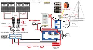
Two MPPT controllers \ Two Arrays (redundancy\as well as to compensate for shade \ etc)
Really looking for major flaws or safety issues....

Thanks in advance. Appreciate the advice. Major Questions:

1.) Overall do you see any safety or major design issues with this layout / Solar portion?
2.) Is 14 AWG suitable between panels and combiners?
3.) Is 10 AWG suitable between MPPT and Batteries?
4.) 25 AMP cut off switches between combiners and MPPT for easy disconnection?
5.) 15 Amp FUSE at Battery In Line MC4 Fuses?
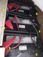
6.) (see pic of my battery bank) unsure which posts to connect to to have it balanced properly
7.) 3x 10⁵ AH AGM Batteries (315 total amps 1/2 useable) - assuming 4 to 5 hours of sun - am I correct to assume I should see about 100 to 125 AH going back into the bank each day?
8.) If I use a plug to 30 AMP cable for my generator, I assume just firing up the generator and flipping on shore power (1600 watts running) about 13 AH an hour going back into the bank? Is my math correct? Anything extra needed other then regular plug to 30 amp plug?
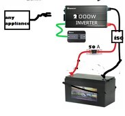
9.) I am considering putting in an invertor. This would be to charge laptops or run small appliances. I would keep everything at (appliances and charges) 1000 watts or less that would use it. (occasional use items) - What would be safe specs and recommendations for an invertor that would not damage my AGM batteries? What posts and wire size would I use to connect the invertor to the batteries?
10.) Is there a way to bypass the invertor if using shore power?
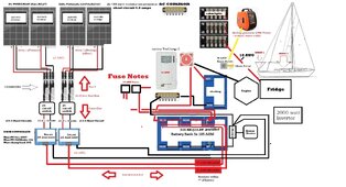
 

Attachments

  • diagram (1).jpg
    diagram (1).jpg
    368 KB · Views: 13
  • batteries.jpg
    batteries.jpg
    136.1 KB · Views: 12
1. One issue - the negative from the solar chargers must go to the load side of the shunt- not directly onto the batteries.

2. 14 will work - I keep all my solar at 10awg. (Less different wires to mess with)

3.Yes just fine - for your size of system.

4. Always nice to be able to turn the sun off for maintenance.

5. You only need solar fuses if going with 3 panels in parallel- and on the other side of the combiner. It won’t hurt where you have them. But not needed (unless there is something in ABCY Codes that I don’t know about - I don’t think there is).

6. Use #1 & #6 OR #4 & #3. You want opposite corners.

7. Four 120w solar panels. Each array will generate 240w - you could use a mppt 100/20 SCC and save a couple of dollars.
480w / 12v = 40amps going in under perfect conditions. being flat 30 amps will probably be as high as you see - 100ah to 125 ah is probably reasonable to go into the battery from solar.

8. Make sure the generator makes the N-G bond - if not there is a plug for that.
That 1600w generator can theoretically charge a 12v battery at 1600w / 13v = 123amps per hour. Way more than the battery can take.

9.if you are adding an inverter, highly consider adding a Victron PowerIn bus bar (look up YouTube to add fuses to it) as a distribution load/charger bus bar. Then move all those lugs off the battery and to the bus bar. (The shunt goes between the battery and the negative bus bar). This will cleanup lots of cables. The inverter cables size depends on which inverter you choose.

10. You want/need a transfer switch priority goes to inverter. Also make sure you have an easy way to turn the inverter off - on 24/7 will be bad for you.

What I really want to recommend is a Victron Multiplus 12/2000 Inverter/charger. But it may be a little too big. It has the transfer switch built in, plus a battery charger, plus you can adjust the incoming amps to fit the power source - 15a for generator- 30a for shore. If you get this get a Cerbo (and touch) to bring all the electrical info into one very informative screen (from shunt,mppt’s and inverter). The Cerbo will act as the inverters on/off/charger only/invert only switch, plus change incoming amps.

If you go with that inverter you can set the inverter output limit lower so you cannot over pull your agm batteries.

I cannot help you know how much load you can safely pull from your AGM batteries. But for occasional use it probably can be quite high.

Good Luck

If any of my answers don’t make sense- let me know and I will try another novel to fix?. Also please update as the project progresses
 
Thanks so much!!!! This was by far one of the most helpful and informative responses Ive had!

1.) adjusted the neg solar mppt on the image. correct?
2.) adjusted the wire size from panels to mppt to 12 instead of 14.
5.) So I can leave the fuses out and keep the 15 amp breakers just before the battery?
6.) added and adjusted battery post numbers... look correct?
7.) so its reasonable to expect around 100 AH per day solar on this setup?

8.) 123 amps an hour? I got 12? I expected that if I ran it approx 4 hours it would put 50 AH back into the battery. Is my math messed up?

10.) The invertor. I am thinking the renogy 2000 watt? I am only selecting appliances that use less then 1000 watts and they will be used sparingly. i.e. induction burner (600-800 watts - maybe 2 times a day for 10 to 15 minutes) maybe a laptop chargers( 150 watts) here and there. Perhaps the occasional 700 watt space heater(while on shore power). i will have invertor with 6-8 feet of the batteries (1/0 wire). SO I am unsure how to wire (what lugs to hook to) this and what you mean by the transfer switch and what to get. I have 3 outlets in the boat for when I am on shore power - and this invertor has two outlets - so I am fine not having a switch for shore or on the hook power.. the outlets existing would only be used on shore power and the invertor outlets would be separate and used from the banks while on the hook....

Generator - NG bond - I cant seem to find anything in the docs (https://m.media-amazon.com/images/I/C1HD7kWiQYS.pdf) ETQ 2000 watt generator / 1600 watts running. I assumed that I could use the standard cable (https://www.amazon.com/Amp-Up-Marine-RV-Cords/dp/B07FKTZGX4 - 30 amp female to) to go from regular outlet on generator to the 30 amp shore power. would this all be correct items? the NG bond thing is confusing me if I need a part or if my generator has it.
 

Attachments

  • diagram.jpg
    diagram.jpg
    378.5 KB · Views: 6
Last edited:
1. Yes correct
2. ?
5. Correct.
7. That high is likely only on almost “perfect” days. No clouds, no haze, no shade on the panels. You will likely have some days you get more and most days you get less and a few days you wonder - why did I put solar in???
8. That is the watts your generation can output - then you need to convert from 120v to 12v (I.e. the battery charger), likely your battery charger is only 12 to 15 amps.

The N-G (Neutral-Ground) bond is important and both your inverter and generator should handle it correctly in all situations. (Really the inverter).

You must have one - and only one place where the 120v neutral and ground are connected.

When plugged in to shore (or at your home) this will be at the service entrance. No N-G bond should be at the inverter or generator.

When on generator, the generator should have this wired in, if not there is a plug adapter you can get that creates the N-G bond. But when on generator there should be no N-G bond at the inverter.

When on inverter, the generator ‘s N-G bond should be isolated with a transfer switch (this is why transfer switches switch both hot and neutral at the same time). And there should be a N-G bond at the inverter. The inverter needs a relay to switch the N-G bond on and off. Many cheap inverters do not have that.

The reason I really like the Multiplus line from Victron is it handles the N-G bond correctly in the inverter (I am sure there are others that handle it correctly too - but not all do). When on Generator or Shore it passes the N-G bond to them. Then when on inverter it handles it itself.

The N-G bond is important because if a failure happens and a hot wire rubs against the metal equipment enclosure the outside metal is now electrified. With a correct N-G bond the power flows back on the ground completing the circuit and tripping the breaker. And you know you have a problem. Without a N-G bond the metal frame is now electrified with 120v and the equipment may still work. When you touch it it will depend on if there a return path what happens. You may feel nothing, you may feel a slight tingle, or you may get a full 120v shock - all depending on how well you and your surroundings complete the circuit. This can also raise all kinds of issues with electronics (those expensive things in boats that you relay on).

On a boat make sure the N-G bond is all correct. Read the manual before you buy the inverter and make sure it handles it correctly. It have “heard” that the Renogy inverters are not handling the correctly- if they don’t - you need to understand what they are doing and then make your system work it correctly.

You can know if the generator has a N-G bong by using your DMM (Digital Multimeter and measuring connections between the N and G on the generator. (Most do - but not all so verify).
So i think I am understanding all BUT the NG bond and the "when on invertor" "when on generator" "transfer switch"- if I have the 2000 watt portable ETQ generator (1600 watts continuous). My goal was to ONLY use this to occasionally top up the batteries if I have multiple cloudy days and am off grid (i.e.e just pull out of a locker, plug the cable in, run it for 4 or 5 hours). Its not something that would be regularly used and would be stowed most of the time. My "assumption was" i get the cable that has a normal plug that goes int the generator and the other end plugs right into shore power (30 amp) and just fire it up and charge the batteries..... so I am confused where the invertor plays into this?

I also don't get the transfer switch ....That whole piece is confusing me... my plan was just install the invertor directly on the batteries (unsure the posts you suggest), use it occasionally and turn it off when I am not using it. It would ONLY be used while off-grid (1000 watt appliances or less - really 800 watts or less) - when hooked to shore power the invertor would be switch off and the regular outlets that are hooked to shore power would be used. perhaps the transfer switch is to switch the outlets to invertor instead of shore power? If that is the case I dont think that would be needed as I would be plugging right into the invertor with appliances... sorry new to this but you have been very helpful!

Also have heard invertors and load can danage AGM batteries? with a 1k or 2k invertor and only using it occasionally for appliances under 800 watts would that be an issue?


this wasnt a generator that would be permanently attached? so the on invertor and on generator is confusing me. did the additions on 6.) added and adjusted battery post numbers... look correct?
 
Last edited:
The battery posts look ok - your not trying to put too much on any of them are you.

Read up on the N-G bond - YouTube is great. Electricians on YouTube cover it well. Once you understand the why and how we do it for our homes, then you take the knowledge and apply it to the boat.

The boat complications are you can have three different sources of power, but you MUST have one (and only one) N-G bond active.

As long as the generator is bonded (need to verify that), then your shore and the generator is fine. Then you need to figure out how the inverter you selected is bonded (it may or may not be) and how to make sure there is one and only one bond in all three power source options. With a boat you may have options with the panel selectors. (I don’t know).

In my case, I have a MotorHome, a built in generator, and a Victron Multiplus 12/3000.

When on shore the shore has the bond, a transfer switch isolates the generator completely.

When the generator starts up, the transfer switch switches the hots and neutral to the generator, so the generator supplies the power and has the bond. Even if the shore power cable is connected, my rig has no electrical connection to the shore hots or neutral. When the generator is off the transfer switch opens the connection to the generator so no bond can happen there (the same thing occurs on the Shore power).

When the Multiplus inverter is running with no shore or generator power, it closes a ground bond relay inside it, thus making the N-G bond.

Many cheap inverters do not even try to get it right. And so they are playing with your safety. As long as everything is ok - no issues, but when issues happen there is no safety net,
So I just contacted Renogy and they said they have n-g bond in their invertors. I do not know about the generator.... Ok so back to the generator\shore power\transfer switch. I think we may be just not understanding the set up or i am communicating it wrong.

So the shore power on my boat connects to the 30 amp port on my boat - i have a switch on my panel that says shore power on and off. The generator is stowed and never hooked up. if I were to use the generator...i would be away from shore power and would plug the generator directly into the 30 amp shore power plug, flip the shore power switch, and fire up the generator.... so the two questions would be.... is that the transfer switch you are talking about? or is one not needed if shore power and and generator are never hooked up at the same time?

I would keep 4 or less connections per post on the batteries. I think thats the rule.

What is the cable I could use on the generator for the n-g bond you recommened? would that solve the question on the generator?>
 
You have a completely manual transfer switch- I.e. your hand plugging the cord in.

Just verify the generator’s has an electrical connection between the neutral and the ground and it is good.

The inverter has a n-g bond- so you are good there.

Then you just have one problem to solve that is how to wire the inverter so that when the generator or grid is active, the N-g bond in the inverter is out of the picture.

Can you add a power transfer switch that has shore power for one side and inverter power on the other? (I like automatic things so I can’t screw up).

There are several ways to solve that problem.
 
ok so if I tie the invertor directly to the batteries + & - using 1/0 wire (as renogy said to do) could I just use a 32 AMP isolator switch to disconnect the invertor when on shore power? Would that be a solution? then when I hook up shore power I disconnect the invertor....when I am sailing or on the anchored out I can flip on the the isolator and then power on the invertor....?
 
I am assuming the 32A isolation switch is on the A/C side of the inverter. If Yes, then that should work out perfectly!

Don’t forget to ground the inverter frame.
 
I am assuming the 32A isolation switch is on the A/C side of the inverter. If Yes, then that should work out perfectly!

Don’t forget to ground the inverter frame.
Appreciate your help. So, I called renogy and spoke to them. They stated just connect the invertor + & - right to the battery, So i'd put the isolator between the invertor and the battery. The invertor wont be hooked up to outlets, just leaving existing ones only on with shore power. the invertor has 2 or 3 outlets and thats what i'd use while away from shore. just for light use. Is that correct? do you thin the AGM bank is safe if I am using the invertor for items that are 800 watts or less with occasional use? ive heard you can damage agm batteries with invertors....
 
On the inverter setup - is your plans to not have anything plugged into the 120v A/C side of the inverter until you want to use the ______ (say toaster - wait too big - say charge the computer). Then you plug that into the inverter use it and then unplug it.

If that is the case and your inverter’s A/C plugs are NOT tied into the boat systems, then you do not even need the transfer switch. The N-G bond of the inverter will only be for the stuff that is plugged into it. The other inverter’s 12v can remain tied to your battery with no issues (with a fuse obviously), then when you need it - you turn it on and when do ne don’t forget to turn it off.

Sometimes the hardest thing on sites like this is you type one thing, I interpret it a different way, type something and it takes us both a while to “get on the same page”!

An inverter will not damage agm batteries just using it- unless you have:
1. Too big of an inverter and too big of loads for the battery bank.
2. Use it often enough that you keep running the batteries down and not getting them fully charged back up.

You are just fine on #1 and #2 will depend on watching your battery monitor and manually recharging when needed.
So, I have regular outlets that only work when I am on shore power; that will stay like that and have nothing to do with the invertor - i will nevet mix the two. The goal is to have an invertor attached to the batteries so that when I am off of shore power I have an option to charge laptops and such. Those item will be plugged directly into the invertor and not have anything to do with the boats main outlets (which only work on shore power). Two Separate Systems.

This is really only to offer occasional regular devices power when off of shore power. When we hook up to shore power the invertor will not be used and the regular outlets will work again.

The invertor is 2000 watts -- the house bank is 300AH of AGM (may add another 100 AH battery at some point). even though I am putting in a 2000 watt invertor my goal is to never exceed appliances with 800 watts or more and those will be shore periods. i.e. 100-200 watt laptop chargers....maybe a small 600-800 watt induction burner (that would only be used for maybe 10-15 minutes at a time - which should only use maybe 10-20AH? )....watching battery levels to ensure it never exceeds 50% drop.

Would this be fine? I'd still like to use 1/0 wire / use an isolator to be able to take the invertor completely offline, use a 50 amp fuse on the invertors positive, and like renogy stated wire directly to the battery. Does all that sound ok?

The invertor would be off when not being used and when I hook up to shore power I would isolate it just to be safe, thoughts?

if i isolated just the invertor part it would look like this (remove the whole rest of the electrical system)
 

Attachments

  • sample inv.jpg
    sample inv.jpg
    42.2 KB · Views: 2
Last edited:
Ok one issue - the 32A isolation switch is way too small. (Many posts ago I was thinking it would be on the A/C side. The DC side, a 2000w inverter can draw:
2000w / 12v = 166amps

So a 32a switch and a 50a fuse are both DOA.

You said Renogy recommended a 1/0 wire that will do about 150 amps *12v = 1800w. You want full sized cables from the battery to the inverter- don’t skimp in this area even if you never plan on going over 800w - the inverter can. Use this large size on the main trunk line of the battery.

Because the inverter’s AC is not mingled with the boats. You could use the inverter while the generator is going or while on shore power. You have two completely different AC grids. (Not that either of those really make sense - but there is no danger from the N-G bonds because the systems are totally different. Before I was thinking you were going to energize the boats plugs - that was what was making the complications.
 
One more thing…

Battery Bus Bar.

You have a LOT of connections onto the batteries. It would make a lot of sense (if there is room and budget), to have bus bars for both the batteries and the loads/chargers.

Look at getting two Victron PowerIn. One is a battery bus bar - each battery is connected directly to the PowerIn with a same length cable. Then from that is connected to the shunt and then to the other bus bar called the load/charger bus bar. All your chargers, inverter, Dc fuse box, etc, etc is connected to this one. You can add fuses to it too (see YouTube).

If you don’t go with that one look for a good blue sea or BEP marina one - whatever fits your space the best.

Good Luck
 
Ok one issue - the 32A isolation switch is way too small. (Many posts ago I was thinking it would be on the A/C side. The DC side, a 2000w inverter can draw:
2000w / 12v = 166amps

So a 32a switch and a 50a fuse are both DOA.

You said Renogy recommended a 1/0 wire that will do about 150 amps *12v = 1800w. You want full sized cables from the battery to the inverter- don’t skimp in this area even if you never plan on going over 800w - the inverter can. Use this large size on the main trunk line of the battery.

Because the inverter’s AC is not mingled with the boats. You could use the inverter while the generator is going or while on shore power. You have two completely different AC grids. (Not that either of those really make sense - but there is no danger from the N-G bonds because the systems are totally different. Before I was thinking you were going to energize the boats plugs - that was what was making the complications.
so 100 AMP fuse? 200 amp fuse? - also can you recommend an isolator switch that would cover this? I see where a surge could be 160 to 190 amps....even though the usual current would be under 20 amps?

maybe this? https://www.amazon.com/Circuit-Breaker-Trolling-Waterproof-Protection/dp/B0C4DBXKHX
 
Im thinking the 1000 watt invertor would be the best. I was looking at the size of the 2000 and think it may be more then I need. Since I am not going to be using anything over 1000 watts - 2k might be over kill.
 
I have not used those high amp cheap Chinese circuit breakers - so not much help there, I have read on this site that others don’t like them- high resistance &voltage drop, and they don’t pop when they should- either too low or too high. So be careful.

If you want a switch on the inverter I would suggest something like:

Blue Sea Systems 6006 m-Series Battery Switch ON/OFF with Knob, Red https://a.co/d/iLnu7EP

Only the positive line needs switching.
 
Back
Top