


Taco Supremo
New Member
Hello all,
Thank you for reading and all the contributions you've made in the forum up to this point. I'm a big fan of Will!
I'm building a 24 quart milk crate power station for my suv. 12V will be used to run the fridge and some led lights around camp and charge phoned etc.
I plan to use a 100ah lifepo4 battery and charge off alternator, shore or solar.
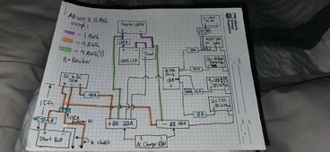
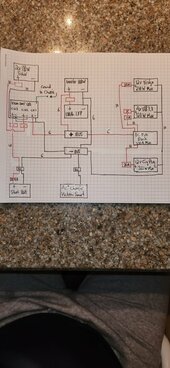
I've attached my diagram.
I have some questions around wire size, wire configuration and fusing.
The crate is removable. The alternator power and chassis ground will connect to the crate via a 175A Anderson Quick Connect and charge as we drive. Solar will only be charged when stationary from 2x100w foldable solar panels.
AC shore powerwill be used to charge prior to trip and when possible at campsites. 1000w inverter to power 20v chainsaw battery charger (600w) and two way radio batteries.
Questions:
1. Green wires can be 4AWG?
2. 40a or 50a breaker (blue sea 285) considering under hood temp, using 4AWG, and <20ft total loop?
3. For the fuse between dc charger and +Bus, can it be 40 if main fuse on start batt is 50? Does it matter?
4. Do I need a fuse on PV + line into MPPT?
Equipment list thoughts so far
Vic orion tr 12 30
Vic smart mppt 12 20
Vic smart shunt
Blue sea breakers, busses, and fuse block
Thanks in advance for any and all guidance and critique! I'll post pics as I build!
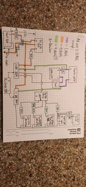
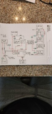
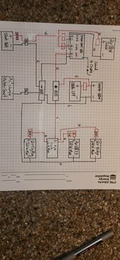
Same pic just different orientations...
Thank you for reading and all the contributions you've made in the forum up to this point. I'm a big fan of Will!
I'm building a 24 quart milk crate power station for my suv. 12V will be used to run the fridge and some led lights around camp and charge phoned etc.
I plan to use a 100ah lifepo4 battery and charge off alternator, shore or solar.
I've attached my diagram.
I have some questions around wire size, wire configuration and fusing.
The crate is removable. The alternator power and chassis ground will connect to the crate via a 175A Anderson Quick Connect and charge as we drive. Solar will only be charged when stationary from 2x100w foldable solar panels.
AC shore powerwill be used to charge prior to trip and when possible at campsites. 1000w inverter to power 20v chainsaw battery charger (600w) and two way radio batteries.
Questions:
1. Green wires can be 4AWG?
2. 40a or 50a breaker (blue sea 285) considering under hood temp, using 4AWG, and <20ft total loop?
3. For the fuse between dc charger and +Bus, can it be 40 if main fuse on start batt is 50? Does it matter?
4. Do I need a fuse on PV + line into MPPT?
Equipment list thoughts so far
Vic orion tr 12 30
Vic smart mppt 12 20
Vic smart shunt
Blue sea breakers, busses, and fuse block
Thanks in advance for any and all guidance and critique! I'll post pics as I build!
Same pic just different orientations...


 ;
;
")

 .
.


 .
.


 ,,, I think in your case, I would be using the “dual fuse” terminal on to of the battery positive & The Safety Hub 150;
