diy solar

diy solar

Possible bad battery in a bank - how to test/find?

karamazov

New Member
Joined
Oct 13, 2022
Messages
30
Hi y'all.

Have a bit of an issue that hopefully someone can help me with. Some info on my system:

I have a DIY whole home system with 2 parallel 48v 308Ah LiFePO4 battery banks I built myself, 16 cells each (new ones from EEL Battery, so they should theoretically be decent quality). I'm using the Overkill solar BMS to manage each one. Hooked up to a Sol-Ark 15k.

Tonight I had an outage. Looks like the grid went down for a few minutes. However, I lost power when our batteries should have kept us up for those few minutes. Upon digging through the data in PV Pro I saw that the battery kicked on as expected, but then shut off just a few minutes later. I also noticed that recently, the SOC shown on the inverter has been dropping from 50% to 0% instantly sometimes.

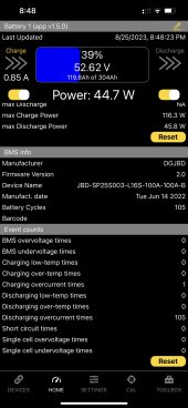
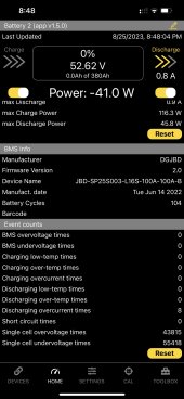
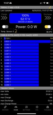
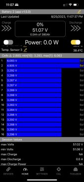
So I went out to read the data directly from the BMSs and low and behold...battery bank 2 shows 0% SOC. Battery bank 1 was at 39%, which seemed expected given we just had an outage. However I also looked at some of the data on bank 2 and saw that it's registered 10s of thousands of cell under/overvoltage events, whereas bank 1 has 0.

Anyone have any ideas what could be going on here, or any recommendations on troubleshooting steps? It would be a pain to have to tear the entire bank apart and test everything one by one - I'll do it if I have to but trying to avoid that.

BMS screenshots attached if that helps.
 

Attachments

  • image_123986672 (1).JPG
    image_123986672 (1).JPG
    104.8 KB · Views: 11
  • image_123986672.JPG
    image_123986672.JPG
    104.7 KB · Views: 10
The single cell over/under voltage events on battery 2 is concerning. What do the individual cell voltages look like?
 
I’d be interested in a cell voltage. That may be able to find the cell.

Could be as simple as a loose nut.
 
There are also a fair number of Discharge Overcurrent events. How much power are you trying to raw from this system? What loads are on the inverter?

If the only errors were over or under voltage cell or pack, then I would look for a bad connection somewhere. I think that is what you have in Battey2. Any time there is a high current, the voltage of some cells go out of range. Any slight poor connection between cells will do that.

But you also have an over current even for every charge cycle in Battery1. My guess is that when Battery2 goes into a protection shut down, all the current is put on Battery1 causing it to shut down from too much current. This is a common issue when you depend on multiple batteries to provide enough current to run the system. With only 2 strings, it would be a good plan for each string to be able to handle the full current. If you had 3 strings, then having each string able to support over 50% would still allow for one going offline.

As for finding the issue, can you run on just Battery2 and load the system to about 50 amps on the battery. Then measure the voltage across each buss bar from battery terminal to battery terminal. In a perfect world, there should be no voltage as you are measuring across a solid bus bar. But at 50 amps, 0.020 volts (20 mv) would not be too bad. But if you find one at 0.080 volts, no we are getting into a problem, and over 0.100 volts is very bad. Depending on where the balance leads are connected, a single bad bus bar connection can cause 2 cells to measure bad. Typically, charging would cause a cell over voltage and discharging would cause a cell under voltage. But some balance lead setups can cause the cell next to the bad connection to also read the opposite direction.

I also had a condition where my battery shut down because of a faulty pin on the balance lead connection at the BMS. That was very odd as it caused the cells on both sides of the bad connection to read virtually zero volts. But when I loaded the cells inside of the BMS, it pulled current just fine, and all the cells measure fine, even probing the BMS wires. I was nearly convinced the BMS had just failed. But when I measured the cell voltages on the BMS PC board, I saw that those 2 were flat out wrong. The crimp on pin was done poorly and the wire corroded a little and stopped making connection. Once I replaced the pin, it went back to working perfectly.

My point here is you need to measure to see if the cell voltage is really going out of range, or is it a bad high current path, or a bad balance lead measuring path.
Ah your theory does make a lot of sense.

My system is whole-home, so we had the AC running and everything at the time. If the grid goes down (at night) and we have over ~10kW worth of loads running, the Sol-Ark inverter won’t actually draw more than that from the battery only anyway so it’s not really possible in my setup to ensure I have enough battery to power my entire house if the grid randomly goes down. It’s mostly for emergency backup to keep the essentials running in the case of a prolonged outage.

I will try to test the battery out as you described, maybe I didnt do a good job with one of the connections.
 
Ah there it is....I don't know how I didn't notice this the last time I checked the BMS. Voltage readings on cells 1 & 2 are going wacky, oscillating between unrealistically high and low very fast. I'll have to check the leads and/or the BMS itself to see if there's some problem with the connection.
 

Attachments

  • image_123986672 (4).JPG
    image_123986672 (4).JPG
    99.8 KB · Views: 6
  • image_123986672 (3).JPG
    image_123986672 (3).JPG
    99.9 KB · Views: 5
  • image_123986672 (2).JPG
    image_123986672 (2).JPG
    98.4 KB · Views: 5
Ah there it is....I don't know how I didn't notice this the last time I checked the BMS. Voltage readings on cells 1 & 2 are going wacky, oscillating between unrealistically high and low very fast. I'll have to check the leads and/or the BMS itself to see if there's some problem with the connection.
Check that the insulation on the BMS lead ring terminal for those cells isn't holding the nut and post apart (had that happen) and re-tighten all the nuts. That was the solution every time it's happened to me.
 
Check that the insulation on the BMS lead ring terminal for those cells isn't holding the nut and post apart (had that happen) and re-tighten all the nuts. That was the solution every time it's happened to me.
This was basically the issue. Literally all it took was two quarter turns on the battery lug on cell 1 positive where the lead was attached and boom, problem gone! ? Now I feel silly.

Guess I should have done my due diligence with checking the torque on everything the first time, but at least it wasn't something bad!

Thanks to all for your advice.
 
Back
Top