diy solar

diy solar

Possibly overclamped EVE LifePo4s prismatics; what went wrong, and have I broken them?

Aren’t the terminals part of the cells?
Yess...
The cathode is attached to one terminal the anode is attached to the other terminal and they are hanging in a pool of electrolyte that is contained in an aluminum box. The terminals have a mechanical connection through holes in the top of the aluminum box.
Think of a bus bar like an old-timey bottle opener. The motion of cell A expanding and contracting can impose a prying moment on cell B thus weakening the mechanical Bond of the terminal to the box.
I am also concerned about any motion potentially loosening terminal bolts.
I am not concerned about extending the life outside of what I just described.
 
My exact thoughts. Its not for extended life of the cells, but less stress on terminals.
According to teste done (check compress or not thread), it's primarily to extend battery life (nr of cycles).
It's to prevent cell's deformation on the charge cycle to become permanent.
If property compressed, the new life threatening will be calendar ageing.
 
According to teste done (check compress or not thread), it's primarily to extend battery life (nr of cycles).
It's to prevent cell's deformation on the charge cycle to become permanent.
If property compressed, the new life threatening will be calendar ageing.
I understand that. But my reasoning was not to extend cycle life, but to prevent terminal stress.
 
I see what you did there.
I guess it goes into failure of cells, have many people reported cells failing due to catastrophic cell loss (voltage dives due to terminal weakness causing an open circuit) or just sever reduction in capacity?
 
So, I'm going with basically loose hand-tightness on the bolts, and will watch the slightly deform cells like a hawk for the first few cycles. The Daly BMS should indicate any major issues with them.
 
Here is my compression solution. I wanted to apply the force in the middle of the big surface, and I have a beefy bar and a plate to spread the pressure a bit. My theory is that I don't need to have pressure on the whole surface. The plate covers the full width but only about a third of the cell height. I didn't calculate the M10 nut tensions, I only used my "feeling". The battery is now up and running with a JK BMS.
A big advantage with having the rods over/under the cells is that I get a very narrow build. The stacks can be placed very close to each other. Watch out for the necessary isolation, don't trust the thin blue plastic wrapper. Also, the stack can be lifted by holding the ends of the upper rod (a job for 2 persons, at least with my back).
IMG_20221221_212546.jpg
 
The load seems to spread in a very narrow band of the largest battery side.
As the side wall is very thin, I wouldn't be very happy with this setup - but that's me...

Also EVE schematics show 3 rods each side for a reason... I would suspect load spread...

Hope the best for you, but would rather have a different design for me
 
The cells will expand around the bar, you need to support the entire cell face.
 
Here's why I didn't bother.

Have you watched his video when he was testing the capacity of the Mason 280Ah battery he assembled? IIRC he got less than 250Ah from them. 280Ah cells with less than 100 cycles IIRC.

P.S. Checked Andy's test. He got 252Ah. The guy makes great videos but I would follow the manufacturers recommendations.

Springs have two major benefits - you don't wonder what the compression is and 3-4mm cell expansion will have little impact on it.

The cells in the 1st post are a little over-compressed, but unlikely damaged. I would reduce the compression force.
 
Last edited:
So a one year (or 202 "cycles" since going live late last January, according to the BMS) follow up, should anyone else who has numptastically overcompressed their batteries Google this thread.

Obviously, YMMV, take this with a pinch of salt and apply your own judgement and reasoning; there's a lot of energy stored in these things.

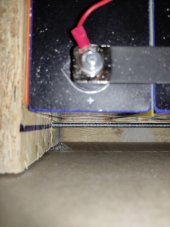
Six bolts clamped back up to finger-tight (call it 1Nm). When the system went live I monitored them neurotically for the first few weeks while getting the system working generally, and didn't have any issues with the batteries. Lots of other problems to sort out with the inverter in the first month or so, resulting in a number early hours of the morning, head scratching at fault codes, in underpants, in a freezing cold loft moments; but never any hassle from the batteries.

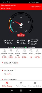
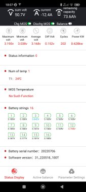
This is how they're doing today after pulling about 70% out of them - 0.152V differential. They charge overnight at 56V/50A with the 150A BMS doing as much active load balancing as it can (from memory this is only an amp or two, from the highest voltage cell to the lowest during charging).

Curiously, there's no longer any sign of deformation ?.
 

Attachments

  • Screenshot_2023-12-15-18-07-33-682_com.inuker.bluetooth.daliy.jpg
    Screenshot_2023-12-15-18-07-33-682_com.inuker.bluetooth.daliy.jpg
    142.4 KB · Views: 15
  • Screenshot_2023-12-15-18-07-42-489_com.inuker.bluetooth.daliy.jpg
    Screenshot_2023-12-15-18-07-42-489_com.inuker.bluetooth.daliy.jpg
    154.3 KB · Views: 15
  • IMG_20231215_181356.jpg
    IMG_20231215_181356.jpg
    93.7 KB · Views: 15
resulting in a number early hours of the morning, head scratching at fault codes, in underpants, in a freezing cold loft moments;
Damn... another thought I can't now unsee :(

Seriously though...
.152v is quite the delta.
Yes... not good, but it's only cell 3 that is low, according to the screen.

I'd be looking to charge them all up to whatever you have set to 100% (3.45V / 3.5V maybe?) and then disconnect the inverter, get your isolated bench PSU out and top up cell 3 to match the other cells.

Do monitor carefully the voltage of cell 3with a multi-meter as you charge it, so as not to overcharge it - they will increase voltage quickly in the top knee.
 
Last edited:
Back
Top