diy solar

diy solar

Random power outage EG4 6500 split phase

I'll check it later today, at get back to you
Took me a few days to get to it, I'm reading 27VDC (+) to ground and 215VDC (-) to ground on both of my PV arrays.
That's great, if you don't mind to try something, you might not not like the reading you get, check readings from the positive or negative terminals on PV to earth ground and let me know if you have potential.
 
My inverters are doing this exact same thing. I think it is caused by the sun when it is rising and the panels start to make enough power to carry the load of the house. The inverter switches over to solar but then realizes it doesn’t actually have enough solar to power the load and it hard resets back to utility. It’s super annoying, some mornings it will do it 10-15 times in a half an hour period. Seems to happen to me when I’m in USB.
Can you describe how your system is setup?
 
Others have reported the new Firmware just released has improved the switching. Might be worth it to update before going deeper into his specific setup.
 
Took me a few days to get to it, I'm reading 27VDC (+) to ground and 215VDC (-) to ground on both of my PV arrays.
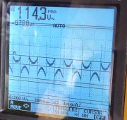
I'm really surprised that you have that low of potential on the positive. Mine has a lot more that that, It changes with the amount of irradiance coming in. In my original setup(Growatt), I found this potential by accident, I felt It tingle when I was washing my panels, and started investigating. No one at SS knew what it could be and I was very concerned about it. I found out on this forum that these inverters are non isolated and that it has bleed through. My positive shows anywhere from 20 to 190V DC and also will read AC with a very odd waveform.
 

Attachments

  • 20220928_181258.jpg
    20220928_181258.jpg
    349.3 KB · Views: 4
Last edited:
Yes, I have been running for about a week using EG4 mode with no interruptions. All batteries are grounded and I used small jumpers on the com ports to ground. I should have grounded my batteries when I installed them however I am thinking the com port might be causing the problem. Purely a guess on my part, I'm just playing with things when I have time. I don't see the harm in grounding the port, it would be great if someone else could verify a standing voltage then ground them to see if it affects their system. I'll draw something up in a bit for a visual and post it.
@Desertdwllr I checked it on my inverters today. I have been testing this system nearly non-stop for over a week and cannot find the cause of an occasional F80 CAN fault that shuts down 2P1 while 2P2 continues to charge the battery. With the one inverter going off, it will trip the GFCIs in my camper, among other things.

My 2P1 inverter was bought in May 2022, and my 2P2 is from late November, after my original 2P2 inverter stopped working. I don't know if it is recent enough to not have the bonding screw or not. I grounded my batteries early on.

When I checked the voltage to ground on the com ports on 2P2 this afternoon, the right port read 0.0V, and the left port read around 0.3V. The ports on 2P1 read anywhere from 1.0V to as high as 2.0V (typical 1.3V to 1.5V).

Have you heard anything else, and do your temporary grounding jumpers still seem to be working?
That’s interesting. So your saying when one inverter faults, both are not shutting down? I thought that was a safety feature when they’re in a split phase pair.
 
@Desertdwllr I checked it on my inverters today. I have been testing this system nearly non-stop for over a week and cannot find the cause of an occasional F80 CAN fault that shuts down 2P1 while 2P2 continues to charge the battery. With the one inverter going off, it will trip the GFCIs in my camper, among other things.

My 2P1 inverter was bought in May 2022, and my 2P2 is from late November, after my original 2P2 inverter stopped working. I don't know if it is recent enough to not have the bonding screw or not. I grounded my batteries early on.

When I checked the voltage to ground on the com ports on 2P2 this afternoon, the right port read 0.0V, and the left port read around 0.3V. The ports on 2P1 read anywhere from 1.0V to as high as 2.0V (typical 1.3V to 1.5V).

Have you heard anything else, and do your temporary grounding jumpers still seem to be working?
Funny you should ask, I was just thinking today how solid my system has been running and I'm afraid to take off my jumpers to further troubleshoot. I did upgrade the firmware in both my inverters to the latest and greatest last week.
 
I'm really surprised that you have that low of potential on the positive. Mine has a lot more that that, It changes with the amount of irradiance coming in. In my original setup(Growatt), I found this potential by accident, I felt It tingle when I was washing my panels, and started investigating. No one at SS knew what it could be and I was very concerned about it. I found out on this forum that these inverters are non isolated and that it has bleed through. My positive shows anywhere from 20 to 190V DC and also will read AC with a very odd waveform.
Sounds like you might have a problem with your panels. The water in the hose creating a path to ground. Are your panel frames grounded?
 
That’s interesting. So your saying when one inverter faults, both are not shutting down? I thought that was a safety feature when they’re in a split phase pair.
When I was flashing the latest firmware my system did the same. Firmware mismatch fault, the inverter I wasn't flashing was charging the battery at full capacity. Also if you turn the inverters off by pressing the front button they will still charge the battery.
 
When I was flashing the latest firmware my system did the same. Firmware mismatch fault, the inverter I wasn't flashing was charging the battery at full capacity. Also if you turn the inverters off by pressing the front button they will still charge the battery.
Ok, was just making sure there’s not some other issue which could shut down one unit while the other one is still inverting.
 
That’s interesting. So your saying when one inverter faults, both are not shutting down? I thought that was a safety feature when they’re in a split phase pair.
When I set up my system, I searched for, and finally found some difficult to find 60A 120V single-pole breakers for my electrical panel. There was almost no one doing AC Input and talking about it at the time, and I asked SS Tech if the two single pole inverters would work as long as they are on the different phases in the electrical panel - instead of running a single two-pole 60A breaker. They said yes, so I left it as it was. I don't think that has anything to do with the issue I have been having, but it has caused me to look at potential problems with that in mind and to consider whether it is a factor or not.

When this F80 fault occurs in 2P1 (it has happened 3 times in the last week or so), it doesn't fully shut down. The display stays lit with it beeping and flashing the F80 code and the LED light bar on 2P1 will be off. When the F80 Fault occurs on 2P1, the 2P2 display may no longer show the 2P2 designation on the display, but it will clearly be charging the battery at a rate that sounds, audibly, less aggressive than 60A - that's what I have always tried to set as the Max Utility Charging Current in Setting 11. At that point, 2P2 is no longer inverting to 120V (immediate indication is that the LED shop light I have connected to the 2P2 phase in my Load Center is not lit) and about half the time it seems, the GFCI's in the camper get tripped when this happens (but not always).

After getting everything shut down, I am finding that it may take 2-3 restarts to get everything reconfigured and running properly again. There will always be some resetting of the LED light bar configuration on either or both inverters, most of the time the 2P2/180 configuration has to be redone on 2P2, and other random settings may have to be reset to get back to normal.

The system ran well overnight with about 1500W constant load from a space heater. I had Setting 12 set to 60% SOC and Setting 13 set to 70% SOC, and it completed the cycle twice between 60% and 70% SOC during the night (I chose 60% only because the batteries were at 67% as the sun was going down yesterday afternoon and I wanted to see what happened as PV Input became intermittent - hopefully as the Inverter was switching from PV to Grid as PV went to 0W).

When the sun came up this morning and the first PV was recorded, it happened just as the SOC hit 59% and the inverters were gearing up to go into Grid Mode to charge the batteries back to 70% again. The inverters dropped the charge rate to maintain the 59% SOC instead, and when the PV dropped to 0W a few minutes later, the inverters ramped up and started charging the batteries again for a few minutes. At 62% SOC, the PV came back for good, and the inverters dropped the Grid contribution back to where it makes up the difference between PV and Load to maintain SOC at 62% until PV takes over.

The one thing that I changed last night was that as I was going through the settings on both inverters again, I found that during the last F80 event, Setting 11 on the 2P2 inverter had changed back to the Default setting of 30A and the setting on 2P1 was still at 60A. I changed Setting 11 on 2P1 back to the 30A default setting, and as of this morning, PV has just exceeded 1000W and Grid power is dropping toward 0W.

My lesson #1 for today: Check every setting on each inverter at least every morning (or even more frequently) while testing, especially after experiencing any kind of glitch. Restart the inverters as needed to verify that updated settings have taken properly.

My lesson #2 for today: Back off from the max charging rates and see it the system will run without issues before doing additional testing.

My lesson #3 for today: Don't use Solar Assistant to try to set the battery management settings during testing. Make sure everything runs correctly, and that it runs as you expect it to, using Settings 12 and 13 directly on the inverters. Only use Solar Assistant for monitoring and data capture (I'm exporting the CSV data to Excel to do deeper analysis on things I can't see directly in the SA app).
 
If you have enough solar to run an electric space heater, you should take a look at moving to solar vacuum tube hot water. You only need to run the circulation pump which will save you lots of power.
 
If you have enough solar to run an electric space heater, you should take a look at moving to solar vacuum tube hot water. You only need to run the circulation pump which will save you lots of power.
Thanks. I am just using the space heaters (4 of them that I have used around the farm for various reasons over the past few winters) for testing for now, as they make it easy to set up anywhere from 0 to 6000W in ~750W increments. I can set them so that they come on and off randomly by setting the thermostats different, etc.

I have purchased two mini-splits to install if I can ever get things running smoothly and reliably, one is the EG4 hybrid solar/grid unit, and the other is the Innovair 38 SEER unit that works down to -22 degrees F. I am also looking at putting in a 300'-600' geothermal ground loop (about 5' deep) to use a water-source heat pump instead of an air-source unit (those units are cost prohibitive for now).

I'll have a look at the solar vacuum tube hot water system - the way I am configured currently is that I have all of my solar equipment in a separate building/mechanical room/lab, and that has my focus for now. It's out in the open with good sun, while the house is 300' away with trees and shade...
 
Sounds like you might have a problem with your panels. The water in the hose creating a path to ground. Are your panel frames grounded?
Yes they all are frame grounded, also if you disconnect the panels from the system, the potential goes away, at the panel as well ad at the inverters.
 
My system, Two EG4 6000EX in parallel, 4 EG4 LL VER.1, set on USE, I monitor batteries via SA, and only have 1 NG bond that I know of, Filterguy had me test for NG bond about a month back and the consensus was the the units I had didn't have a NG bond, however I got new units last month and have not checked them yet. See pics attached.
Hello. Have you resolved this problem as I now have shutdown issues as well, and I see in your combiner panel you have a 40 A dual breaker for each inverter input wire, is this so you can shut down one of the inverters if needed? I have just one 60 A dual-breaker in mine with a hot from each inverter on each terminal. Just curious. Thanks.
 
I would venture to assume that the signal ground would be at the same same ground potential as the shield, mine was not.
View attachment 132932

Flexing my MS paint skills here, I tried to capture the DB9 connector terminal, I was able to read around 1.5VAC to ground at the RS232 DB9 connector.


View attachment 132935

View attachment 132936
This is specifically drawn to show case grounding only, the conduits that I have between my inverters, cable gutter and battery rack and sub panel are all PVC/ PVC flex. The inverters have their #6 THHN wiring to ground that I am not showing on purpose. Curious what others are measuring on their DB9 connectors and if jumpering them to ground stops the power cycling. This might have nothing to do with anything, just ruling things out at this point.
@Desertdwllr
I came across this thread after I had this F80 issue when I added more panels to my system and the inverters tried to put out more than about 50A of current to the batteries. No issue with F80 CAN errors until I added more panels, so it seems to be leakage from the MPPT to battery charging circuit causing the comms interruption when it's over a certain current.

I measured the same AC voltage you observed from the comms shield to ground and it seemed to go between .2VAC and 1.4VAC in sync with the charge current. More charge current, more VAC on the DB9, seeing the 1.4VAC when battery charge current was around 100A. I was able to observe this when the panels were going in and out of cloud shade. This was with no grid input and no loads.

I'm curious as to why the serial port connectors on the inverter are not case grounded to the inverter that would already be grounded to the rest of the system ground. Perhaps sanding off some of the paint on the inverter case under the DB9 connector would have the same result to properly ground the communications ports? I'm going to start with your alligator clamp method and if that resolved the CAN issue I will see if I can get a proper case ground on those DB9s.
 
Did anyone find a solution for random outages and F80 faults with the 6500s? I received replacement inverters and get one or two outages a week.
The returned inverters would do it daily.
 
Did anyone find a solution for random outages and F80 faults with the 6500s? I received replacement inverters and get one or two outages a week.
The returned inverters would do it daily.
I have the same question, got my split phase set up w 12 Lifepowers and getting F80 errors as well.
 
I have the same question, got my split phase set up w 12 Lifepowers and getting F80 errors as well.
I had 2 strings of PV on 2p1 and one string on 2p2. I was getting F80 shutdowns for 3 days in a row at high PV input. I would reset and they would shut down a couple minutes later. I turned off PV to 2p1 and the shutdowns stopped. I ended up removing a string from PV1 on 2p1 and have not had any more F80s in a week. I have still had a few random shutdowns, only noticeable because my oven clock blinks when I lose power. Today I reconnected the string that was on 2p1 to 2p2 and didn't have any F80s so far. I don't have any real idea why or if the second string on 2p1 was causing an F80. I have been trying all sorts of stuff to make it stop and this has done it so far. Could also be a coincidence. I have sent in for the 18kpv upgrade, can't deal with these any longer. Maybe a problem with 2p1 PV1 causing the communication error?
 
Did everyones issues go away? Or did everyone just give up?
My F80 faults went away with the PV string changes above listed in my last post. I am getting the random shut downs without faults or codes. Happens at night too, so kind of ruling out panel issues. Shut downs are 3 to 0 times a day can't find any common denominator in the data to give me a clue of why. Going to switch to USE instead of EG4 to see what happens.
I have tech support working on the issue but they were slow to get to next step. They want more useless photos and meter readings to get through their red tape to go to T2 level support. Nothing special about my system so one would think they have resolution without knowing much about my system. Others with lifepower batteries are getting F80. I switched to Lib from EG4 and disconnected comms thinking that would work short-term (and it did yesterday, charged over 60 A on 2P1 and no fault. But today it faulted. Support suggested only use EG4 or user with 56 and 54V, so will switch to that tonight. I only get F80 when 2P1 exceeds 60A. ???? I updated all the firmware on both inverters a few days ago, didn't help.
 
Did everyones issues go away? Or did everyone just give up?
My F80 faults went away with the PV string changes above listed in my last post. I am getting the random shut downs without faults or codes. Happens at night too, so kind of ruling out panel issues. Shut downs are 3 to 0 times a day can't find any common denominator in the data to give me a clue of why. Going to switch to USE instead of EG4 to see what happens.

I'd be interested in seeing results if you were to drop the VOC of each string (2 per AIO) below the 4000W/250V allowed in the other clones of this inverter.
 
just give up?
Pretty much but figured out a work around.

charged over 60 A
The problem I have here: When my system is <99% SOC and there are intermittent clouds, the system will F80 on 2P1 when loads are >25-30A. But, when at 99% SOC it will not F80 when a cloud crosses the sun. Neither will it F80 when the skies are clear at any % SOC.

What did I find that prevents the F80 error: Set the maximum charge current to 30A or less on those "special days". It is unfortunate the equipment fails but this "work around" does alleviate resetting the system several times on laundry day or pool heater day.

Maybe max charge can be set higher than 30A, IDK...I haven't experimented.
 
Pretty much but figured out a work around.


The problem I have here: When my system is <99% SOC and there are intermittent clouds, the system will F80 on 2P1 when loads are >25-30A. But, when at 99% SOC it will not F80 when a cloud crosses the sun. Neither will it F80 when the skies are clear at any % SOC.

What did I find that prevents the F80 error: Set the maximum charge current to 30A or less on those "special days". It is unfortunate the equipment fails but this "work around" does alleviate resetting the system several times on laundry day or pool heater day.

Maybe max charge can be set higher than 30A, IDK...I haven't experimented.
I think you really need to hold your tongue right when you set these things up and hope. I will not even touch a button to change the display on fear of going back to F80s and random shutdowns. I'm sure I'm on borrowed time though. :(
 

diy solar

diy solar
Back
Top