diy solar

diy solar

Renogy 500a Battery Monitor Mystery

Pivo

New Member
Joined
Jan 6, 2022
Messages
14
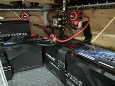
In my trailer, I have 600watts of solar coming into a 60a charge controller and going to 2x300amp/h Li batteries and 2000w inverter (all Renogy). I using a Blue Sea Safety Hub fuse block. I am using a Renogy 500a Battery Monitor to keep an eye on things. Please see pictures (I can provide better pics if needed). The system generally works very well (DC and AC). The issue I have is with the Battery Monitor. I believe I have it properly connected (but open to feedback) with the battery (-) to B- and the fuse block (-) / SSC (-) to the P-. On the monitor, I get the up and down arrows as I would expect. But then...when I turn off the interior lights to the trailer, the battery monitor screen starts to flash as though something is wrong. For the life of me, I cannot figure this out. I would be grateful for any and all suggestions. Much appreciated!


IMG_2909.JPGIMG_2907.JPGIMG_2906.JPGIMG_2905.JPGIMG_2903.JPGIMG_2902.JPGIMG_2909.JPGIMG_2907.JPGIMG_2906.JPGIMG_2905.JPGIMG_2903.JPGIMG_2902.JPGIMG_2899.JPGIMG_2898.JPG
img_2909-jpg.216871
 

Attachments

  • IMG_2909.JPG
    IMG_2909.JPG
    328.7 KB · Views: 38
Battery bank (-) to battery side of shunt. Other side of shunt to everything else - loads and sources. NOTHING but shunt connected to battery (-)

Shunt (+) power wire to battery (+).

Is it wired like that?
 
Yes, I believe that's how it is. B- of shunt has only battery (-)(yellow arrow, pink arrows). Other side of shunt P- has SCC- (smaller black wire) and the negative to the fuse hub (green arrow). These pictures should offer a better view. Notice that the monitor also shows only 41 minutes of time remaining when the batteries are at 100%. Does that look right?

2024-05-21_18-14-44.png2024-05-21_18-15-40.png2024-05-21_18-16-57.png2024-05-21_18-17-49.png
 
Yes, I believe that's how it is. B- of shunt has only battery (-)(yellow arrow, pink arrows). Other side of shunt P- has SCC- (smaller black wire) and the negative to the fuse hub (green arrow). These pictures should offer a better view. Notice that the monitor also shows only 41 minutes of time remaining when the batteries are at 100%. Does that look right?

View attachment 216895View attachment 216896View attachment 216897View attachment 216898
The Renogy monitor is a TF03K. I have three different systems with that monitor. My experience with it is that the time remaining feature can behave oddly under certain circumstances. I've seen mine indicate there is zero time remaining right after it's fully charged, but before any real load is turned on (most often seen on a small portable power station if charge it up but only use it later). As soon as I turn on a load of any significance, it readjusts to a reasonable number and stays that way until I repeat the charge and hold action. Seems it holds the countdown to charge completion rather than immediately showing full time left.

As for the flashing: my monitors pulse whenever the batteries are charging.
 
Last edited:
The Renogy monitor is a TF03K. I have three different systems with that monitor. My experience with it is that the time remaining feature can behave oddly under certain circumstances. I've seen mine indicate there is zero time remaining right after it's fully charged, but before any real load is turned on (most often seen on a small portable power station if charge it up but only use it later). As soon as I turn on a load of any significance, it readjusts to a reasonable number and stays that way until I repeat the charge and hold action. Seems it holds the countdown to charge completion rather than immediately showing full time left.

As for the flashing: my monitors pulse whenever the batteries are charging.
Thanks! So, maybe it's all good and I should just ride it out for a bit? I can do some field testing with higher loads and see what happens. It's good to know that the gremlins have not overtaken the monitor!
 
Also, if any of the members have a look at my set up and have suggestions, please fire away! I'm hoping to improve this design and optimize overall performance. I'm happy to share the schematic as well (knowing I'm a DIYer!).
 
Battery bank (-) to battery side of shunt. Other side of shunt to everything else - loads and sources. NOTHING but shunt connected to battery (-)

Shunt (+) power wire to battery (+).

Is it wired like that?
would you not have to connect the - solar wire, from the mppt, also to the negative of the battery..Thanks
 
would you not have to connect the - solar wire, from the mppt, also to the negative of the battery..Thanks

If you want to bypass the shunt, so it never shows charging by solar, yes, that's exactly how you do it.

If you want the shunt properly installed so that it shows all discharge and charge:

Battery bank (-) to battery side of shunt. Other side of shunt to everything else - loads and sources. NOTHING but shunt connected to battery (-)

Shunt (+) power wire to battery (+).
 
There is a red wire running from the red on/off switch mounted above the inverter, which wire runs to the 150A MRB fuse mounted on the pos battery post.

Is that red wire properly sized in relation to the fuse?

Assuming a 12v system, I would guess that the wire would need to be at least 4 AWG?

I cannot tell the size of the wire from the photos.
 
But then...when I turn off the interior lights to the trailer, the battery monitor screen starts to flash as though something is wrong.

What do you mean by flash? Back-light or random stuff on the display, If the former, does it have a light sensor for the back-light?
 

diy solar

diy solar
Back
Top