ImAnIdiotPleaseBePatient
Solar Enthusiast
- Joined
- Dec 10, 2022
- Messages
- 456
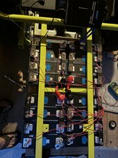
So I connected the batteries with the busbars.
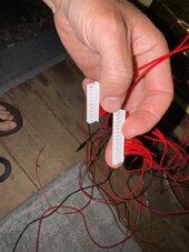
Then I connected the ring terminals to the JK bms leads, and attached them as follows
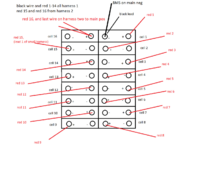
--On the 15 pin connector, black to the main battery negative, and 1-14 to battery positives on cell 1-14.
--On the 11 pin connector, lead-1 to positive of cell 15, and the last lead to the main positive
Next, before plugging any of the plugs into the BMS or connecting BMS to battery negative, I took my multimeter and checked voltage differential on the back of the 15 and 11 pin connectors. First, checked black wire to red1, black to red2, etc etc. I saw...
black to red1 = ~3.2
black to red2 = ~6.4
etc, all the way up to ~52v from black wire to the lead connected to the main battery positive.
Having seen this in Youtube vids, I felt pretty confident to connect the BMS to the main battery negative, and plug in the 15 and the 11 pin connector to the JK.
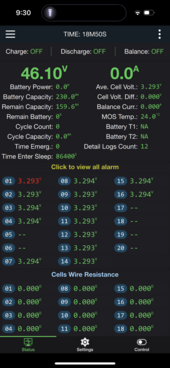
Next, I turned it on, and connected to the app via bluetooth. The BMS only shows cell 1-15. Any ideas? It appears I am missing a cell, but the back of the 11 and 15 pin connectors all showed jumps of 3.2v, so I can't figure out why a cell would be showing as missing from the BMS app.
On the positive side, voltages across the "15" cells were identical, not that it matters too much because I know the voltage curve is flat here. Also should note that the JK is showing the pack voltage as ~48-49v, instead of the 52v of the pack
Then I connected the ring terminals to the JK bms leads, and attached them as follows
--On the 15 pin connector, black to the main battery negative, and 1-14 to battery positives on cell 1-14.
--On the 11 pin connector, lead-1 to positive of cell 15, and the last lead to the main positive
Next, before plugging any of the plugs into the BMS or connecting BMS to battery negative, I took my multimeter and checked voltage differential on the back of the 15 and 11 pin connectors. First, checked black wire to red1, black to red2, etc etc. I saw...
black to red1 = ~3.2
black to red2 = ~6.4
etc, all the way up to ~52v from black wire to the lead connected to the main battery positive.
Having seen this in Youtube vids, I felt pretty confident to connect the BMS to the main battery negative, and plug in the 15 and the 11 pin connector to the JK.
Next, I turned it on, and connected to the app via bluetooth. The BMS only shows cell 1-15. Any ideas? It appears I am missing a cell, but the back of the 11 and 15 pin connectors all showed jumps of 3.2v, so I can't figure out why a cell would be showing as missing from the BMS app.
On the positive side, voltages across the "15" cells were identical, not that it matters too much because I know the voltage curve is flat here. Also should note that the JK is showing the pack voltage as ~48-49v, instead of the 52v of the pack