diy solar

diy solar

RV battery upgrade

rfguy

New Member
Joined
Aug 25, 2020
Messages
19
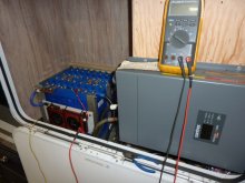
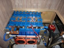
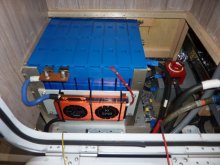
I had posted earlier about wanting to upgrade my RV batteries and was not sure which battery to use. I made the decision to purchase the Fortune 100Ah LiFePo cells. I bought 16 for a 4S4P pack and a 200A BMS. I already had a Xantrex XC inverter/charger. The pack feeds a junction box through a 250A Blue Sea fuse holder Buss fuse. In the junction box is a bus bar feeding an 80A breaker for the RV leveling jack system and a 60A breaker for the RV utility circuits. The bus bar feeds the inverter through a Blue Sea 2 position 300A disconnect switch mounted on the junction box cover. The first position of the disconnect gives the inverter a soft start through a 10 ohm 25W resistor and the second position bypasses the resistor. The batteries come with covers for the terminals and makes for a clean safe install. I am really impressed with these Fortune batteries.
 

Attachments

  • Inverter_battery install.jpg
    Inverter_battery install.jpg
    81.3 KB · Views: 65
  • Battery_bms_inverter-disconnect.jpg
    Battery_bms_inverter-disconnect.jpg
    95.7 KB · Views: 66
  • Batteries with caps installed.jpg
    Batteries with caps installed.jpg
    82.8 KB · Views: 65
The US based vendor refers to it as Simple BMS but there is no brand markings on it other than what may be the model J05W-FH05. I have been charging the pack at 80A for the last hour or so and BMS is cool to the touch. The nice thing about the switch is it can only be turned in the CW direction and is a make before break switch.
 
Very nice and clean. Do you have any pictures of how you wired up the resistor for the soft start? How long do you leave it there before turning it to the ON position?
 
Very nice and clean. Do you have any pictures of how you wired up the resistor for the soft start? How long do you leave it there before turning it to the ON position?
Thank you! Unfortunately I did not take pictures of the underside of the switch but it is simple enough to explain. The switch is mounted on a 3/8" aluminum plate on the box cover behind the switch. The ohm value was picked to allow the caps to charge but not with a surge. The highest charge current would be about 1.4A (depending on battery voltage). The highest wattage dissipated if the inverter was turned on in position 1 would be less than 20W. From my tests prior to build the 10 ohm charged quickly that no hesitation is needed in position one. The switch has 2 pairs of contacts. Two labeled 1 and 2. The first position closes the like number pairs, the second position closes all 4. The resistor straddles a #1 contact and #2 contact. Power is fed on the other #1 and inverter fed on the other #2. Pretty simple. I played around with a programmable time delay controller I have but it consumes power. My next step is solar modules and charge controller.
 
Back
Top