


You are using an out of date browser. It may not display this or other websites correctly.
You should upgrade or use an alternative browser.
You should upgrade or use an alternative browser.
RV ToyHauler solar system schematic
- Thread starter Loadtoad
- Start date
") The inverter has internal bonding between the neutral and the chassis ground.
The inverter has internal bonding between the neutral and the chassis ground.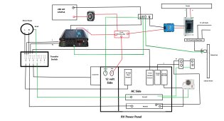
Smokey
New Member
- Joined
- Apr 29, 2021
- Messages
- 40
as shown the converter will be powered off the inverter via the transfer switch, best way I've found is to have a sub panel feet the inverter power circuits and a sub panel.
2. make sure your BMS can power the surge of the inverter
3. how are you fusing the inverter and SCC?
2. make sure your BMS can power the surge of the inverter
3. how are you fusing the inverter and SCC?
One item you may want to consider adding is a Victron battery protect BP65 (or BP100) just before your 12v stuff. That way if you leave a 12v light on and your batteries drain the BP65 shuts down the 12v stuff to stop the drain on the batteries. I like shutting down the loads before the bms low voltage disconnect hits. (Gives solar a good chance to bring the system back).
I got the smart BP65 - that way I can set the cutoff and restart voltages to what made sense for my MotorHome. Added bonus it can also act as an on/off switch.
I got the smart BP65 - that way I can set the cutoff and restart voltages to what made sense for my MotorHome. Added bonus it can also act as an on/off switch.
1. the converter is powered only when shore power is turned on. Position one on switch provides power to the 30 amp breaker which feeds the 15 amp breaker. From the 15 amp it goes thru the transfer switch and then out to the converter on the RV power panel.as shown the converter will be powered off the inverter via the transfer switch, best way I've found is to have a sub panel feet the inverter power circuits and a sub panel.
2. make sure your BMS can power the surge of the inverter
3. how are you fusing the inverter and SCC?
2. No problem with surge, the inverter has a soft start and the BMS handles my loads fine.
3. Looks like that might be a problem? I will order a 70 amp fuse to place between the scc and the positive buss bar to start with.
Last edited:
Smokey
New Member
- Joined
- Apr 29, 2021
- Messages
- 40
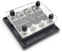
I've been using theses 4 place ANL fuse blocks from SMD, just for installs like yours.1. the converter is powered only when shore power is turned on. Position one on switch provides power to the 30 amp breaker which feeds the 15 amp breaker. From the 15 amp it goes thru the transfer switch and then out to the converter on the RV power panel.
2. No problem with surge, the inverter has a soft start and the BMS handles my loads fine.
3. Looks like that might be a problem? I will order a 70 amp fuse to place between the scc and the positive buss bar to start with.
Attachments
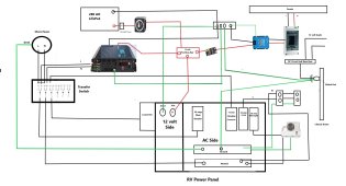
I forgot to place the 150 amp fuse at the battery. Thanks for pointing that out.I would suggest a catastrophic fuse at the battery.

Smokey
New Member
- Joined
- Apr 29, 2021
- Messages
- 40
fuse blockDo you have a link?
eXodus
Solar Addict
- Joined
- Jul 27, 2020
- Messages
- 1,482
Are you trying to reuse the existing converter to charge the LFP battery?
1. Look up the specs if it is compatible.
2. No idea how the Transfer switch is wired inside - but you are potentially creating a loop.
You charge from the converter to the battery - then to inverter which is powering the converter.
1. Look up the specs if it is compatible.
2. No idea how the Transfer switch is wired inside - but you are potentially creating a loop.
You charge from the converter to the battery - then to inverter which is powering the converter.
Whinny
Solar Enthusiast
- Joined
- Dec 24, 2020
- Messages
- 403
You don't need to switch the grounds, a 3 pole transfer switch works fine...
And it's nice to have an enclosure.
And it's nice to have an enclosure.
It pulls a max of 920 watts when running in heat mode.150A from the battery will get you about 1500W out from the inverter. Will that run your mini-split?
When the transfer switch is put to shore power, the ac line and neutral from the inverter are cut off. Only on shore power will the converter run. When the transfer switch is put in inverter mode, the positive power lead from the 15 amp breaker which supplies the converter is cut off at the transfer switch also. The converter can only run on shore power, it has no power when the inverter is running. The ac power panel can provide 40 amps at 13.6 volts to charge the battery if I have no sun. That will be good enough until the sun comes out. If I did not run that 15 amp converter line thru the transfer switch, I would have to manually turn that breaker off every time I switched to inverter power, this way it is automatic.Are you trying to reuse the existing converter to charge the LFP battery?
1. Look up the specs if it is compatible.
2. No idea how the Transfer switch is wired inside - but you are potentially creating a loop.
You charge from the converter to the battery - then to inverter which is powering the converter.
Which solar charge controller are you planning to use? If you're using a Victron solar charge controller, it will need a chassis ground also. My Victron MPPT 100/50 requires that.
A shunt is recommended. It's a better gauge of state of charge than is voltage.
A shunt is recommended. It's a better gauge of state of charge than is voltage.
Heyjimmy911
Let's keep it simple.
I have a few victron solar charge controllers and and I don't have a chassis ground. I did have to return one to victron for warranty replacement. Why do they need the chassis ground? I wonder if that's why one of them failed.Which solar charge controller are you planning to use? If you're using a Victron solar charge controller, it will need a chassis ground also. My Victron MPPT 100/50 requires that.
A shunt is recommended. It's a better gauge of state of charge than is voltage.
I have a few victron solar charge controllers and and I don't have a chassis ground. I did have to return one to victron for warranty replacement. Why do they need the chassis ground? I wonder if that's why one of them failed.
I can't speak to your issues. Perhaps not all of the Victron solar charge controllers have a screw for chassis ground. That might be a good topic to start a new thread if you haven't already.
It has the ground connection, I will post a new diagram. I also believe I need to ground the incoming ground wire from the shore power to my chassis?Which solar charge controller are you planning to use? If you're using a Victron solar charge controller, it will need a chassis ground also. My Victron MPPT 100/50 requires that.
A shunt is recommended. It's a better gauge of state of charge than is voltage.
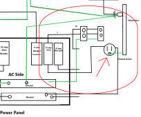
I don't have a definitive answer for you. In my RV trailer, all peripheral AC outlets get a ground wire from the main distribution panel. The main distribution panel gets the ground wire from the Automatic Transfer Switch, which in turns gets a ground from (guessing here) shore power and the on-board generator. So getting a ground from the chassis instead of from the main distribution panel does not seem right.
Similar threads
- Replies
- 4
- Views
- 317
- Replies
- 18
- Views
- 635