diy solar

diy solar

How's does my RV LifePo4 DC Schematic Look?

bass-o-matic

New Member
Joined
Oct 26, 2023
Messages
62
Location
Austin, Texas
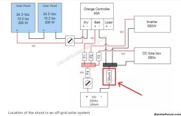
I have a small Self Built RV and I'm upgrading it to LiPo4. See any glaring mistakes in my schematic?

1. I'll probably end up with a Negative/Ground Terminal Block just like the Positive one based on the gauge of the wires.
2. I'm wondering if my 30Amp EG4 Charger is big enough?

Thanks for any input.
RV DC Schematic LiPo4.jpeg
 
I don't see any probs but you really don't need 6 gauge wire from the panels. 40 amp is fine for 3x 100 watt panels in series. Amps stay the same in series and are only additive in parallel.
 
I don't see any probs but you really don't need 6 gauge wire from the panels.
Yes, standard 10AWG solar wire is fine (same as on your panels and the max gauge most MC4 connectors accept).

I wouldn't combine array negative with SCC negative output to battery. Possibly just a drawing shortcut?
 
And for clarity, especially if ordering where your text gets run thru a translator:

LiPo is lithium polymer and there are BMSs for LiPo
LiFePO4 is lithium iron phosphate, aka LFP if you are looking for an abbreviation

not sure how the mashup LiPo4 translates to/from Chinese for example
 
Updated. Note: The 6ga from the panels I built into the trailer walls 10 years ago since I was erring on the side of maybe expanding... who know what I was thinking.
RV DC Schematic LiPo4.jpeg
 
Don’t think a Maxi fuse is rated for AIC for lithium cells.

THe busbar you pictured looks like a Brass manufacture that is good for a 250 amp audio build, but not for a 12 volt 2000 watt inverter. I have one just like that, but did not install it.

Don’t think the inverter DC ground is rated to go in the DC Blue Sea DC Panel. THe inverter could pull up to 200 amps.

Are the batteries enclosed in a unfinsihed metal can?
 
Overcurrent protection on 12v positive feed cables is missing or incorrect value.
Main battery fuse needs to be class T or MRBF, within 6 Inches of battery terminal.
Inverter power is confusing on diagram, assuming it's a 1000 watt, 2000 peak, then main battery fuse at 80 amps is too low.
Charger connects to battery or 12v buss bar via a 40 amp fuse.
All 12v positive connections at buss bar need suitable fuses on the feed cables .

Need a negative buss bar, taking high power negatives via the 12v fuse box is not a good idea. Chassis, shunt, inverter, fuse box, solar controller, charger, all negatives from these to negative buss bar.
Example simple system,
 

Attachments

  • Screenshot_20230905-200359_Chrome~2.jpg
    Screenshot_20230905-200359_Chrome~2.jpg
    357.3 KB · Views: 25
Are the batteries enclosed in a unfinsihed metal can?
They aren't finished but I found this nice Group 27 Stainless box on Amazon. Everything including the BMS will fit nicely. I was going to line the exposed sides of the cells with 2mm of heat resistant silicone pad and Kapton to avoid any abrasion. https://a.co/d/8WgJqn9

I'm working off the assumption that the SOK batts are in metal so that if everything is properly insulated and doesn't move around inside... I'm good to go.

Furthermore... under the batt I'll put a layer of silicone mat and then 2 95f heating pads... thermostatically controlled.
 
Last edited:
2000 peak, then main battery fuse at 80 amps is too low
Thanks for the info! I see that a 2000W inverter at full load could draw 166 Amps. I really doubt I would ever do that. Still, safety first.

1. I found and MRBF Fuse Block that should work... thoughts? https://a.co/d/hKjEErb

2. What fuse size would you put in F1-F4? (There will be a separate MRBF 40 Amp charger fuse).

3. Negative Terminal Busbar. I'm only finding these. And someone mentioned they are not rated? I don't know what the alternative is? https://a.co/d/1VDFWqb

Thanks for any help.
 
Last edited:
Thanks for the info! I see that a 2000W inverter at full load could draw 166 Amps. I really doubt I would ever do that. Still, safety first.
There is a DC LOSS, so at 12 volts with an average efficiency of 85%, it is closer to 200 amps. If the inverter is running at low voltage cutoff, the draw would be 235 amps.


With those numbers, I multiply by 1.25 and wire and fuse to that. I choose the low voltage cutoff amperage. That comes out to 300 amps.

Where as I follow my rules, my guests and family disregard these rules at some point and run the system all out, so I wire to maximums.
 
Overcurrent protection on 12v positive feed cables is missing or incorrect value.
Main battery fuse needs to be class T or MRBF, within 6 Inches of battery terminal.
Sorry to bug... Are these two sentences relating to the same thing? This would be solved by a MRBF fuse within 6 inches of the Positive Terminal right? My BMS is only 120a so I was going to put a 100A MRBF fuse on the battery post. I have a 2000w inverter but all that's hooked up to it... occasionally... is a mini fridge. And that has been working for years... I think it only really draws much/spikes when the compressor comes on.

And I'm not saying, "oh it's been working fine... everything is cool." Maybe I've been lucky. Happy to improve things.

But The BMS will shut down way before I reach the draw of the Inverter. Right?

Or maybe LifePO4 can't provide spikey amps like Lead Acid Can? I think I read that somewhere.... But wait. Amps is amps. If my current Inverter drew too much... it would pop its fuses... I should have stayed in Kansas!
 
Last edited:
But The BMS will shut down way before I reach the draw of the Inverter. Right?
I would think so, but you’d need to check the setup or spec sheet.

I have 2 settings, one for instant off and the other for a sustained 6 seconds that is higher.

I’d also not want to use the BMS as a primary shutoff because if the MOSFETs shorted, now there’s no BMS protection.
 
What I learned today.

1. MRBF Fuses are rated for constant use.... that's one of the primary benefits over a Maxi Fuse.

2. Shrink wrap terminal connector have their OWN special Crimper. (Great, another tool.)

3. DISCONNECT your power supply, adjust the voltage, THEN connect it to your cells to Top Charge them.

4. Your Power supply will switch to CC when the voltage you set it way higher than what is in the cell. Additionally, at least on mine, in CC mode the Voltage will set to 3.66 no matter what you do. It will go back to 3.65 as you get closer to your selected Voltage and it will switch to CV ( Constant Voltage ). Don't panic.

5. Don't trust your Power Supply. Check the cells with a good Voltmeter to confirm where they are in the Topping Charge Process.

Question: A minor point. In the Schematic the Switch is the first thing off the battery and then the fuse. Can I reverse that? Fuse... then switch. So I can be as close to the + Terminal of the Battery with the fuse as possible.
 
Last edited:
Question: A minor point. In the Schematic the Switch is the first thing off the battery and then the fuse. Can I reverse that? Fuse... then switch. So I can be as close to the + Terminal of the Battery with the fuse as possible.
Yes the fuse is first.

3. DISCONNECT your power supply, adjust the voltage, THEN connect it to your cells to Top Charge them.
Very important as in doing that wrongly destroys cells.
1. MRBF Fuses are rated for constant use.... that's one of the primary benefits over a Maxi Fuse.
Another great point. Wish I‘d known about MBRF when I built my system. Only disadvantage is not rated for 48 volt systems, but if you are at 24 or less, that’s fine.
 
Top Balance went well. It helps that I sprung for a Fluke 107. My Radio Shack multimeter from the early 90's was way off. Reading too Low!

Now I'm doing the capacity tests on each cell with the "Hawk" gizmo. Seems to be going well. I set the low voltage cutoff to 2.6. I'm at ~22 amp draw. It's the Max the Hawk will do. Which I understand is not a .2C test but is as close as I can get. .2C would be 56Amps on 280AH cells?

I'm at 220AH on the first cell and still chugging away...

Question: After the Capacity test - all the cells will be at a low State of Charge. Is there any benefit in wiring them in Parallel and doing another Top Charge OR Should I just wire up my OverKill BMS and charge with the EG4 and call it good?

Cheers
 
Question: After the Capacity test - all the cells will be at a low State of Charge.
I prefer to charge them right back up to some set voltage (or top balance if i have the time) while the next one is in the discharge test.

Wondering if you have the 2 wire or 4 wire discharge tester? The 2 wire is notorious for voltage sag and resulting cutoff before the battery "really" hits your low voltage stop point.
 
Question: After the Capacity test - all the cells will be at a low State of Charge. Is there any benefit in wiring them in Parallel and doing another Top Charge
Right now they’d be bottom balanced. I would also top balance them.
Should I just wire up my OverKill BMS and charge with the EG4 and call it good?
that is an option, but it takes a long time and you’d want to set parameters to always top balance above 3.4 volts and keep it there for a whole

I have an overkill BMS and it’s a mystery the current. I think it’s a half amp or amp and that may take days.

I had one cell out of whack from a bad connection and lower. I left it like I mentioned above and came back in 5 days and it was balanced.
 
Back
Top