Our lead acid batteries have finally bit the dust so we're upgrading to LFP. Here's a description of the system design. It doesn't follow all the ABYC recommendations or all the best practices from this thread, but it seems like the right compromise of safety, cost, and convenience for our boat. The house batteries will be DIY 12V using 302 Ah CATL cells and Overkill Solar BMS. They'll be mounted in a box under the quarter berth, so they'll be well above any likely bilge water. I plan to secure the batteries against any motion but not really attempting to maintain compression against cell swelling. Engine starting is with a new AGM battery.
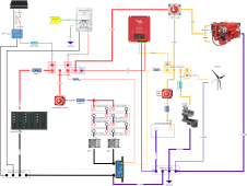
This electrical system is divided into the lithium-powered "house side" (red and black in the schematic) and the AGM-powered "engine side" (orange and purple in the schematic). This division allows connecting the dumb chargers (alternator and wind turbine, which both have simple automotive style regulators for lead acid) and heavy loads (windlass and starter) to the AGM battery. The smart chargers (solar and shore power, both configured with Lithium profiles) and our modest domestic loads (biggest items are fridge and autopilot) to the lithium. A Sterling BB1240 DC-DC charger provides house charging from the alternator or wind turbine. Our alternator is the stock 70A unit that came on the diesel engine, so 40A max seems like an adequate charging current. This DC-DC charger also has a nifty "reverse charging" feature that provides float charging of the AGM battery from solar or shore power. Of course the two negative busses are connected at one place (the SmartShunt) and also have a single-point connection to the bonding system.
We already have a Cerbo GX to collect data from the SmartShunt and MPPT for battery monitoring. I'm installing BlueSea 5191 fuses where any smaller gauge wires connect to the positive bus bars. Both battery banks have 200A primary fuses (class T for the Lithium and AMG for the start battery) and battery isolation switches.
For convenience, I'm keeping the already-existing 1-2-Both switch. I know ABYC doesn't like the Both setting that can parallel the two different battery chemistries. Under normal use we'll always have this switch connecting the alternator and starter to the AGM start battery. In an emergency (such as a battery bank failure), we can disconnect one bank using its isolation switch, then move the 1-2-Both switch to Both to power everything off the remaining battery. The disadvantage of this choice is the risk of mistakenly connecting the two batteries together; the advantage is in an emergency we don't have to mess around with a jumper cable.
I'm sure everyone else will end up with different decisions and compromises. Hopefully this configuration can give you something to think about.
Thanks everyone, for all the helpful suggestions and information here on the forum. We appreciate it.