diy solar

diy solar

LFP & Victron upgrade on 30' sailboat

OS2/Dude

New Member
Joined
Jul 25, 2023
Messages
8
Location
Atlanta, GA, USA, Terra, SOL System
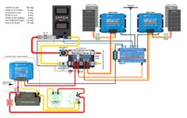
This is my plan for replacing our current two 98Ah AGM batteries in a single bank with a 300Ah LFP battery with Victron Comms. It is all still sitting in my sunroom for the time being, but I hope to get up to the boat this spring to get it installed. I was going to go with a Buck-Boost so I could charge the LFP indirectly from the alternator, but that part is on hold for the time being. One AGM battery will be retained as a start battery for the inboard diesel. Unfortunately, not all items are to scale. Plan currently is to have a common ground. I also got two 115W bifacial panels on sale, so I may put the two 175W panels on one controller and the two 115W panels on the other.

I bought 8mm x 30mm x 200mm copper bar to make link bars to connect the 500A Victron SmartShunt IP65 and 650A Bluesea 3000 disconnect switch to the Victron Lynx. I also got a kit to nickel plate them. I am using 4/0 cable because the battery bank will be about 13 feet away from the Lynx. PrettyGirl Solar with LYNX (2).png
 
Here are a few things you could do to save a little.

1. Instead of the Victron Distributor, get a Victron PowerIn and add fuses (see YouTube on how).

Or if you want to have the LED Lights run there is a YouTube on how to make a power supply cable to operate the lights, however, I don’t believe the distributor will report blown fuses to the Cerbo (without a Lynx shunt).

2. For the 175w + 175w array that will only provide 350w of power a Victron mppt 100/30 will handle that just fine.

3. For the 115w + 115w array a mppt 100/20 would be big enough.

4. The only thing your drawing doesn’t show is where the new battery negative ties into the engine battery negative. (I am sure that’s just an oversight on the drawing- but I figured I would mention it.

Good job on the drawing

Good Luck on the project!
 
Good job on the drawing and planning. The difference between the 98Ah AGM and 300Ah lfp will be incredible.
I bought 8mm x 30mm x 200mm copper bar to make link bars to connect the 500A Victron SmartShunt IP65 and 650A Bluesea 3000 disconnect switch
But, man!!!! This copper busbar is WAY to big for nothing.
That doesn't hurt to be too big (in case of busbars), but 3x25mm (1/8''x 1'') will do the job anytime.
 
Here are a few things you could do to save a little.

1. Instead of the Victron Distributor, get a Victron PowerIn and add fuses (see YouTube on how).
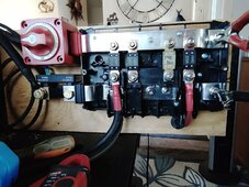
Here is an example of a Lynx power in mod.
IMG_20240204_085927.jpg
Or if you want to have the LED Lights run there is a YouTube on how to make a power supply cable to operate the lights, however, I don’t believe the distributor will report blown fuses to the Cerbo (without a Lynx shunt).

2. For the 175w + 175w array that will only provide 350w of power a Victron mppt 100/30 will handle that just fine.

3. For the 115w + 115w array a mppt 100/20 would be big enough.

4. The only thing your drawing doesn’t show is where the new battery negative ties into the engine battery negative. (I am sure that’s just an oversight on the drawing- but I figured I would mention it.

Good job on the drawing

Good Luck on the project!
 
You design looks fine but it's not clear to me if the coms will play nice out of the Epoch 300 with the Victron gear.

DC -DC chargers are inefficient and don't provide a lot of power. So with this design you will be relient on your solar. Perhaps not a problem in sunny GA, but not an option where I live (PNW).

Also, note that Victron just released a new DC-DC 50amp that has better conversion efficiency. 50amp would likely be too much draw from your alternator at idle however.

Also - I thought the Epoch 300 amp was not yet released? Do you have one of these on order? Or is it also in your
"sun room?"

It specs a crazy surge current 900amps (see below). Would like to see the BMS info to verify that claim....

Ah Capacity: 300Ah
Max Continuous Discharge Amps: 300A
Max Charge Current Amps: 300A
Max Discharge Peak Current Amps: 900A (3 Seconds)
Series | Parallel: Max (4) in Series, Max (4) in Parallel - 4S4P
I received my 300Ah V2 early in January. A SUN ROOM is a room in the house with a lot of windows to let in the sunlight. Currently weather is cold and/or wet, so I'm waiting for warmer/drier conditions before hauling it all to the boat. EPOCH uses a JBD BMS and they communicate with Victron stuff just fine. I just did a small hook up of some of the stuff to get a feel for it (and the ferrule and lug crimping tools) and to configure the CERBO and SCCs.

I decided against using a DC-DC charger for now due to cost, complexity and the fact that since it is a sailboat I don't run the engine that much. I also have a shore-power LFP charger, but I'm fairly confident that the solar will keep it topped up. The two 175W panels kept the 196Ah AGM bank full. Adding two 115W bi-facials should more than make up the difference. I don't have an inverter yet, so my draw is limited to the nav lights/interior lights (all LED), chart-plotter, two MFDs, stereo, 12v TV and a few fans.

I have the two 100W ridged panels I started off with originally and if needed will deploy them with the 175s. (They are normally stowed below.) I also plan to upgrade the 175s to 200s or higher in the next couple of years, so I bought the SCCs a bit oversized for future enhancements.

I can't speak to the 900A peak discharge spec at this time.
 
Here is an example of a Lynx power in mod.
View attachment 193284
So, I m going through this picture, and I dont understand whats going on here.
The Shunt looks like its set up backwards. "to system minus" is set up on the busbar. Does it not actually matter which direction its installed?
Aslo, how did you get your battery switch to fit on the positive busbar? The bolts on mine, are slightly too big for the hole in the busbar, so Im going to have to drill out the hole to allow the bolt through it. Is that what you did?
And where are the power wires for the shunt attached to?
 
So, I m going through this picture, and I dont understand whats going on here.
I can see why you think that. It is set up as a less cost distributor. I have no need for the LED board.
The Shunt looks like its set up backwards. "to system minus" is set up on the busbar. Does it not actually matter which direction its installed?
In fact it very much matters how it is connected. In this set up I have three 100 AH LFP's set up in parallel with ground connected to #1 and power connected to #3. So power comes into the switch then through the "modded" power in. And the ground side to the shunt.
Aslo, how did you get your battery switch to fit on the positive busbar? The bolts on mine, are slightly too big for the hole in the busbar, so Im going to have to drill out the hole to allow the bolt through it. Is that what you did?
Correct I used a 27/64" bit. Less connections is always better in my book.
where are the power wires for the shunt attached to?
Already answered.
 
I can see why you think that. It is set up as a less cost distributor. I have no need for the LED board.

In fact it very much matters how it is connected. In this set up I have three 100 AH LFP's set up in parallel with ground connected to #1 and power connected to #3. So power comes into the switch then through the "modded" power in. And the ground side to the shunt.

Correct I used a 27/64" bit. Less connections is always better in my book.

Already answered.
here are the power wires for the shunt attached to?
Already answered.
No, I mean the two small red wires that come with the Shunt. They go in the little green box on the Shunt that says -Aux & -VBatt +?
Where do you have those two small wires run to?
 
Already answered.
No, I mean the two small red wires that come with the Shunt. They go in the little green box on the Shunt that says -Aux & -VBatt +?
Where do you have those two small wires run to?
My bad. They are attatched to the temp sensor and it is connected to the positive post of the #1 battery.
 
My bad. They are attatched to the temp sensor and it is connected to the positive post of the #1 battery.
What temp sensor?
The schematics I seen, said to connect the Aux, to the vehicle starter, but Im doing this in a camper, so there isnt a starter.
I was just going to attach both of them to a + battery post in the distributor. You think thats would be OK, or does the Aux one need to go to a specific place?
Yes you can.

Does not work use that in the amazon search.
This is in a camp trailer. you can change how you use Aux. in the software. one wire is power and the other is used for the sensor. I suggest that you download the software. There is a demo mode where you can play with and see all of the options for most of Victron sells that is "smart"
 
Last edited:
You have four choices for the aux wire.
1. Leave it off
2. Use to monitor a different battery - starter battery.
3. Use to monitor mid-point voltage
4. Use to monitor battery temperature.

In a camper with 12v battery- monitoring a starter battery and mid- point make no sense. So then either buy the optional temperature sensor if you want/need the shunt to monitor temp or leave it off.
Ill just leave it off then,
I have 4 batteries, with their own JBD BMS and they are right under everything else, so their temp sensors will be adequate, I would assume.
 
Going with the 300Ah LFP battery and Victron Comms seems like a smart move, and the buck-boost for charging from the alternator sounds like a good idea once it's back on track.

Keeping one AGM as a start battery is a good backup plan. Using the 4/0 cable for the distance to the Lynx makes sense. Overall, it sounds like you're making some great upgrades, and I hope it all goes smoothly for you when you get it installed!
 
Ill just leave it off then,
I have 4 batteries, with their own JBD BMS and they are right under everything else, so their temp sensors will be adequate, I would assume.
I added the temperature sensor for my Victron charger devices- I want the solar charge controllers and Multiplus to NOT charge if the battery is below 38F (that’s the temp I remember right now). Then if for some reason that fails then the battery stops the charging at its temperature. I like 2 methods to prevent cold destroying charging. I also look at the Victron app more than the battery info- so it is easier for me to see how cold the batteries are.
 
I added the temperature sensor for my Victron charger devices- I want the solar charge controllers and Multiplus to NOT charge if the battery is below 38F (that’s the temp I remember right now). Then if for some reason that fails then the battery stops the charging at its temperature. I like 2 methods to prevent cold destroying charging. I also look at the Victron app more than the battery info- so it is easier for me to see how cold the batteries are.
That is the reason I went with the temp sensor also.
 
This is my plan for replacing our current two 98Ah AGM batteries in a single bank with a 300Ah LFP battery with Victron Comms. It is all still sitting in my sunroom for the time being, but I hope to get up to the boat this spring to get it installed. I was going to go with a Buck-Boost so I could charge the LFP indirectly from the alternator, but that part is on hold for the time being. One AGM battery will be retained as a start battery for the inboard diesel. Unfortunately, not all items are to scale. Plan currently is to have a common ground. I also got two 115W bifacial panels on sale, so I may put the two 175W panels on one controller and the two 115W panels on the other.

I bought 8mm x 30mm x 200mm copper bar to make link bars to connect the 500A Victron SmartShunt IP65 and 650A Bluesea 3000 disconnect switch to the Victron Lynx. I also got a kit to nickel plate them. I am using 4/0 cable because the battery bank will be about 13 feet away from the Lynx. View attachment 192941

I don't recommend going with the 300AH you should get the 460 epoch as it does not have a metal case. I have seen all too many metal case battery rust especially in marine. Even fresh water boats. Plus the 300 only supports a maximum of 1 battery, so if you later want to expand it won't work.

If you can't afford the 460AH then look at options from victron they have a 330 AH for around 1650

Afew people In my area (Toledo Bend/Gulf Coast) are using the sun fun kits 300 with victron coms and its working well, probably the cheapest option out right now and its not using a metal case and it supports multiple batteries.

Lastly you can always DIY a battery and get a JBD bms along with a TTL to USB adapter with a raspberry PI using the Louis VDW driver, this works extremely well and will save you a good but, but you'll need to make an enclosure. Check 18650batterystore, batteryhookup, sunfunkits, or ezealco.com for cells as they have grade A with test reports.


But yeah the 300AH essentials version of the Epoch is a no go in my opinion for marine, or any other metal battery. Also the limitation of only 1 battery can work is a big issue as well.
 
Back
Top