diy solar

diy solar

LFP and Victron upgrade on 42" sailboat

Lure

New Member
Joined
Mar 12, 2022
Messages
10
I have a 42" sailboat with 3 lead acid battery banks (starter, bow and house) + 560W solar system.
I mainly use the boat without 220V connection (max once a week), with limited engine use (0.5-1 hour / day). Solar currently provides enough charge for my daily use.

I currently have temporary 190Ah lead acid house battery (was put in when old pair of 2x 135Ah died) which I would like to upgrade to LFP.
At the same time, I would like to replace the old 220V charger (without LFP support) with a Victron MultiPlus Compact inverter/charger. I want like to keep as much as possible of the existing installation as it is quite good (oversized cables).

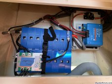
The current installation looks like this (drawing based on my observations/understanding):
- The starter battery is used only for the engine, the bow battery is used only for the bow thruster, and the house battery is used for the anchor windlass and all other loads.
- Current 220V 40A charger has 3 outputs and charges all three batteries.
- 115A "dumb" alternator is connected to all three batteries with 3-port charging separator.
- 100v/50a MPPT solar charge controller is connected only to house (service) battery.

sailboat-42feet-original.png

I plan to upgrade the system with the following equipment:
- 200Ah marine grade LiFePo4 battery with built-in JBD BMS with BT control (with 5 year warranty, do not want to mess with own build)
- Victron MultiPlus Compact 12v/1600va/70a inverter/charger which will provide us 220V electricity up to 1300W everywhere (computers/gadgets, occasional hot water boiler 800W, vacuum 600W...)
- Victron Orion-Tr Smart 12/12-30a DC to DC charger for alternator to LFP charging
- Victron SmartShunt for SOC of house battery
- Victron Cerbo GX and GX Touch 50 for monitoring (local and remote)

This diagram is my current understanding of what the upgrade would look like with minimal wiring changes:
sailboat-42feet-lfp-victron.png

The old and new setups are missing only one thing: solar charging of the starter and the bow battery. The new setup with MultiPlus Compact also does not provide 220V charging as it only has one output (the old charger had 3 outputs). Most of the time, the starter and bow battery will be charged via the alternator (as the engine runs while they are in use), but that does not help when the boat in port or at anchor for several weeks.

I have read old threads with similar needs:

The conclusion there is to put an additional DC-DC charger from the LFP house battery to the starter and bow battery. I think this might be a small 5-10A charger (AMP-L-START has been suggested) that provides more or less trickle charge.
However, my concern is that I would create charging loop (circuit): starter - alternator - DCDC - LFP - DCDC - starter.

Is this the right way to do it or should I do it differently?
Are there any other concerns with the above upgrade suggestion?
 
The thing I would be worried about is your windlass kiling the FET based BMS in your "drop in" battery. Yes, your Windlass may not draw much current when it's moving, but if it stalls out, and when it's starting up, it can have a huge (but brief) current spike. This is a recipe to rapidly kill a FET based BMS.

You'll also want some sort of pre-charge circuit, even if manual for the same reasons due to the input capacitors in the MultiPlus. This is largely for the same reason as above, and basically to combat huge inrush currents when flipping that switch.

If I was you, I'd have your Thruster, Starter, and Windlass all together since you'll almost always be using them while the Engine is running anyway. (I can't think of the last time I tried to raise anchor while purely under sail).
 
Note ABYC and ISO require the safety disconnect to disconnect everything , this would include the solar controller.
 
Note ABYC and ISO require the safety disconnect to disconnect everything , this would include the solar controller.
Well, given that he’s using a drop in battery, this isn’t a compliant system to begin with. The internal bms will have its own shutoff for protection the one illustrated in the schematic is for boat systems and isn’t the safety disconnect.
 
Regarding solar disconnect: they are connected with MC4 plugs that can be used as safety disconnect. But will discuss with electrician about standard requirements.
 
@svagres: I agree regarding windlass. It is hooked to service battery as windlass was basic equipment and bow-thruster was an option that came with own battery. They still hook windlass to service battery. I will probably rewire windlass to bow battery.

Solar disconnect: misunderstood it at first, yes they would need to be hooked behind safety disconnect.

I have now got a copy of ISO 13297:2020 and ISO TS 23625:2021 and I see where the problem is. Internal BMS is supported by ISO:
4.2 There should be a BMS installed to control all installed lithium-ion batteries and maintain the battery manufacturers specified safe operating limits. NOTE A BMS can be internal or external to the battery.
However these requirements are harder:

8.4 HVE/HVC — The BMS protects a lithium-ion battery from an HVE by initiating a multistage HVC consisting of the following steps:
— it should provide a stop charging signal to each charging source; provided for the operator, clearly perceptible from the main helm position;
— if stopping the charging sources does not stop the HVE, an alarm (visual and/or audible) should be
— if the operator fails to stop the HVE, the BMS should initiate an isolation of the sources that are creating the HVE.
8.5 LVE/LVC — The BMS protects the lithium-ion battery from an LVE by initiating a multistage LVC consisting of the following steps:
— it should provide an audible and/or visual alarm to the operator, clearly perceptible from the main helm position, that indicates that the SOC of the lithium-ion battery bank is approaching the low SOC threshold specified by the manufacturer;
— if the operator fails to prevent the LVE, the BMS should initiate the disconnection of non-essential electrical consumers;
— if this does not prevent the LVE, the BMS should disconnect all electrical loads.

The above is not possible with internal BMS as there is no HVE/HVC and LVE/LVC signals from the battery BMS. So if I understand correctly, there is no way you can have ISO compliant installation with drop-in 12V batteries (like BattleBorn, LIONTRON,...). I am quite surprised as I have seen so many boat upgrades done with drop-in replacements.
 
@svagres: I agree regarding windlass. It is hooked to service battery as windlass was basic equipment and bow-thruster was an option that came with own battery. They still hook windlass to service battery. I will probably rewire windlass to bow battery.

Solar disconnect: misunderstood it at first, yes they would need to be hooked behind safety disconnect.

I have now got a copy of ISO 13297:2020 and ISO TS 23625:2021 and I see where the problem is. Internal BMS is supported by ISO:

However these requirements are harder:


The above is not possible with internal BMS as there is no HVE/HVC and LVE/LVC signals from the battery BMS. So if I understand correctly, there is no way you can have ISO compliant installation with drop-in 12V batteries (like BattleBorn, LIONTRON,...). I am quite surprised as I have seen so many boat upgrades done with drop-in replacements.
Yes the view is that ISO will require different. “ drop in “ batteries that essentially have external bms
 
I think ISO 13297:2020 and ISO TS 23625:2021 requirements for "drop-in" LFP are appropriate and more clearly stated than ABYC. Hopefully the LFP manufacturers will respond soon to the need for a Canbus connection to shutdown charge devices.
 
I think ISO 13297:2020 and ISO TS 23625:2021 requirements for "drop-in" LFP are appropriate and more clearly stated than ABYC. Hopefully the LFP manufacturers will respond soon to the need for a Canbus connection to shutdown charge devices.
Yes I think we shall see networkable batteries , all ready there from the likes of Victron , hopefully the new NMEA 2000 PGN for battery management /power control can provide some basis for common CAN networking standards.
 
This project was delayed and updated:
- using LiFePo4 cells instead of replacement battery pack
- using REC 2Q BMS with precharge and Victron support (CAN)
- using Wakespeed WS500 alternator regulator with Victron support (CAN)
- using 2x Victron DC-DC 9A chargers for maintenance/charging of Starter/Engine and Bow lead-acid batteries

Spectrum-LiFePo4-ws500.drawio.png

With REC BMS I can be ISO compliant (HVE/HVC, LVE/LVC disconnect) and with Wakespeed I get most charge out of alternator.
I have decided to keep anchor winch on LiFePo4 battery as the current should not be problematic for 550Ah pack.

Anything else I should improve/change?
 
Still feel like the windlass should be on a Gel or Mat battery so you can beat the heck out of it and not feel concern about the BMS. Could you increase the bow thruster battery bank and run both? By run both not to mean running both at the same time as that is unlikely. Making an assumption enough space in the bow for increased batteries also.
Have not seen mention about Make/Model, only 42'
 
In my experience, Lifep04 batteries are far superior for thruster use as they do not have the voltage drop under load that AGMs do. This means your windlass performs better and doesn't heat up as much. The issue with off-the-shelf Lifep04 batteries is that most are limited by their bms to much lower current than a thruster needs and are therefore not suited for this purpose. So, one other option for your windlass and thruster battery/bank, if you are a hands-on type of person, would be to build your own Lifep04 batteries from suitable cells. For a sufficiently sized battery, the loads on the battery should never deplete it in normal (intermittent) use. If you accept this premise, and monitor state of charge appropriately after use, you can use any inexpensive bms to control the charge side.

I've had great success with such a system for years now, done the Great Loop and more without an issue. For example, in the photo below, the cells are 60A 3.2V in a 4S4P configuration. This yields a 12V battery with 240Ah capacity. My thruster draws 400A. In 10 minutes of use per day (quite a lot), this would remove 67A from the battery. My windlass draws 100A. If used for 10 minutes per day, this would add another 17A. Total discharge 84A. You could run this profile twice and still have 30% capacity left. Just an idea...

I would definitely recommend keeping your engine start battery separate from other battery circuits and use an appropriate switch to parallel this battery with the house bank in the event it should fail to start the engine. As mentioned above, I would use one battery for the thruster and windlass only.
 

Attachments

  • IMG_2468.jpeg
    IMG_2468.jpeg
    1.3 MB · Views: 8
I will first try with current connection of windlass to service battery - with 550Ah and REC BMS I do not expect it to trip the BMS to shutdown the LFP battery.

Bowthruster will stay on lead-acid for now, I use it rarely. I might later upgrade to LFP bank also for bow battery and then I could rewire also windlass to that battery (shorter wire). It should probably be wired this way from the start, but I suppose the thing is that on Bavaria windlass is standard, while bowthruster is optional equipment and it seems that they always wire windlass to service, to simplify their build process.

I have now found VRC-200 charge reference controller from Nordkyn Design from NZ. I am now considering to use this alternator regulator (instead of Wakespeed WS500), as it has one major benefit: it does not require modification of my Mitsubishi 115A alternator (field wire required for WS500). From other aspects it provides similar features (temp regulation in alternator, voltage and current regulation by VRC). With this setup I would keep ECS163 and leave bow and engine battery also hooked to alternator.
 
Last edited:
I have now finalised the design - high-resolution PDF is here: Spectrum-LiFePo4-v65-rec-vrc.jpg

What has changed:
- TBS 300A T-class main fuse
- using TBS Battery Protect Relay as main charge/discharge disconnect
- TBS positive bus bar for load + chargers
- REC ABMS main relay is connected to REC Precharge that does open/close pulse signal to TBS Battery Protect Relay
- using Nordkyn VRC-200 alternator controller - directly controls Mitsubishi 115A alternator via V-sense
- ECS163 is still used to separate alternator charge to all three batteries (protection of alternator to LFP disconnect)
- VRC-200 Charge enable signal is controlled by REC ABMS via Charge optocoupler (with pull-down resistor)
- added 25A automatic breakers to DC-DC chargers (both sides)
- added solar disconnect (DC 20A breaker)
- changed MPPT output fuse to 50A automatic breaker
 
One new item you may want to look at is the Zuse alternative regulator

One of the places selling it.

It looks new & nice.
 
Back
Top