diy solar

diy solar

How would you connect the wires, Can you help?

NBs

New Member
Joined
Feb 28, 2024
Messages
15
Location
Finland
Hi All!

Intended to replace 4*6V 230A AGM batteries 2*280A lifepo4 "drop in".

I have purchased an srne DC-DC 50A charger / mppt regulator.

And new AC-DC 40A charger. The intention would be to leave the old AC-DC charger to serve the bow thruster and starter battery banks

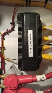
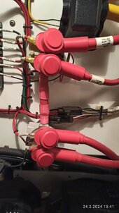
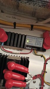
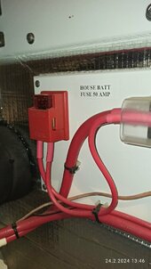
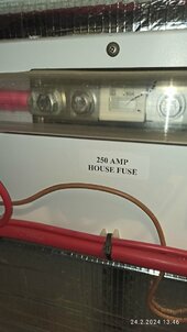
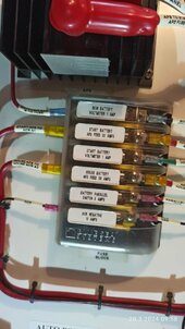
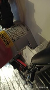
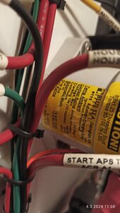
Attached is a picture of battery management now.

How would you connect the wires, Can you help?

Best regard
NBs
Finland


IMG_20240229_111522.jpg
IMG_20240302_105639.jpg
 
Last edited:
How would you connect the wires, Can you help?
The existing system uses the EMERPARALLER ACR relay to parallel the starter and house batteries. In emergency, manual control can activate this relay to allow house battery to start engine.
A further ACR relay allows Bow battery to be charged from the alternator, the manual overide can parallel starter and bow batteries.
The shore charger seems to charge the starter and house batteries via the APS, is this a diode splitter? Again further information on this APS would be useful.

In simple terms you are replacing the ACR relay with the DC to DC

This is my interpretation of the system, you need to confirm that the ACR is voltage sensed, perhaps a picture or manufactures data.

If you disconnect all cables to A2 terminal on the ACR the starter battery is now isolated from the house battery.
Disconnect at the ACR, A1 to start APS fuse.
Disconnect existing shore charger at output of 40A fuse and reconnect to A1. Note the APS is redundant and can be taken out of circuit.

Wire up your new battery bank with a suitable master fuse at the battery positive. Depending on local regulations this may need a ClassT or HRC fuse, MRBF may be acceptable. Connect to main DC panel.

DC to DC unit. Connect input via fuse ( 80A) to A1 starter solonoid, output to house battery via a fuse (80A) ( or fuse as recomended in unit instructions).
New charger Connect to house battery via fuse.
To make the install easier use a positive buss bar, master fuse to buss bar, then fuses from buss bar to DC to DC, new shore charger, and DC panel.

Not shown on you diagram were isolation switches for the batteries, adding power isolation switches is recommended.

As discussed, the modifications will lose the emergency house battery to starter switching. It may be possible to modify the existing ACR to act as a power relay.

I suggest you fully evaluate the existing systems operation and understand how and why its configured. There may have been modifications that differ from the diagram.

Again working from a diagram withour access to the setup to verify operation as suspected, its not easy to suggest modifications.

Hope this has been helpful.

Regards Mike
 
  • Like
Reactions: NBs
Thank you Mike for taking the trouble to analyze my situation.

I am quite sure that the graph corresponds to reality (only solar control house battery). I'll take better sharp photos and information next time I go boating. Here are a few shots.

I have a Blue sea electrical panel with fuse switches for all DC devices, motor and main switch, as well as a digital display V/A, in addition to a separate cabinet for AC electricity. The electricity should be in accordance with ABYC, the boat is made by US (Nordic tug)IMG_20240320_100233.jpg
 

Attachments

  • - bus baar.jpg
    - bus baar.jpg
    91.8 KB · Views: 6
  • start arc and house arc reley.jpg
    start arc and house arc reley.jpg
    92.8 KB · Views: 4
  • ARC batterylink bluesea 7600.jpg
    ARC batterylink bluesea 7600.jpg
    86 KB · Views: 4
  • IMG_20240224_134637.jpg
    IMG_20240224_134637.jpg
    84.1 KB · Views: 4
  • house fuce 250A.jpg
    house fuce 250A.jpg
    79.3 KB · Views: 6
  • IMG_20240320_095805.jpg
    IMG_20240320_095805.jpg
    97.4 KB · Views: 3
Last edited:

Attachments

  • IMG_20240304_105934.jpg
    IMG_20240304_105934.jpg
    80.8 KB · Views: 1
  • IMG_20240304_110025.jpg
    IMG_20240304_110025.jpg
    88.2 KB · Views: 1
Last edited:
The existing system uses the EMERPARALLER ACR relay to parallel the starter and house batteries. In emergency, manual control can activate this relay to allow house battery to start engine.
A further ACR relay allows Bow battery to be charged from the alternator, the manual overide can parallel starter and bow batteries.
The shore charger seems to charge the starter and house batteries via the APS, is this a diode splitter? Again further information on this APS would be useful.

In simple terms you are replacing the ACR relay with the DC to DC

This is my interpretation of the system, you need to confirm that the ACR is voltage sensed, perhaps a picture or manufactures data.

If you disconnect all cables to A2 terminal on the ACR the starter battery is now isolated from the house battery.
Disconnect at the ACR, A1 to start APS fuse.
Disconnect existing shore charger at output of 40A fuse and reconnect to A1. Note the APS is redundant and can be taken out of circuit.

Wire up your new battery bank with a suitable master fuse at the battery positive. Depending on local regulations this may need a ClassT or HRC fuse, MRBF may be acceptable. Connect to main DC panel.

DC to DC unit. Connect input via fuse ( 80A) to A1 starter solonoid, output to house battery via a fuse (80A) ( or fuse as recomended in unit instructions).
New charger Connect to house battery via fuse.
To make the install easier use a positive buss bar, master fuse to buss bar, then fuses from buss bar to DC to DC, new shore charger, and DC panel.

Not shown on you diagram were isolation switches for the batteries, adding power isolation switches is recommended.

As discussed, the modifications will lose the emergency house battery to starter switching. It may be possible to modify the existing ACR to act as a power relay.

I suggest you fully evaluate the existing systems operation and understand how and why its configured. There may have been modifications that differ from the diagram.

Again working from a diagram withour access to the setup to verify operation as suspected, its not easy to suggest modifications.

Hope this has been helpful.

Regards Mike
Hi Mike!

Thank you for your time to consider and solve my problem with the wiring, replacing the boat agm home bank with lifepo4.

I got the job done yesterday and everything seems to be working as it should.

I respect you, thank you!

NBs
 
Back
Top