diy solar

diy solar

SAFETY AWG 7 CABLE FORWARD TO 8 AWG CABLE

BUNYIP BILLY

New Member
Joined
Apr 21, 2024
Messages
10
Location
AUSTRALIA
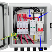
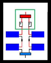
Installed in my recently purchased 4 string combiner box is a busbar connected with 7 awg cable . Is it safe to connect the combiner box ( 7 awg ) to the charge controller ( yet to be purchased ) with 8 awg cable ( as recomended by the manufacturer of the charger ) or should I rewire the combiner box output from the busbar , via the circuit breaker , to the mc4 connectors at the combiner box output connectors with 8 awg cable ? Thanks ...
 

Attachments

  • 2024-04-22 16_47_02-COMBINER BOX.png - IrfanView (Zoom_ 2120 x 990).png
    2024-04-22 16_47_02-COMBINER BOX.png - IrfanView (Zoom_ 2120 x 990).png
    1 MB · Views: 14
Probably, but it depends on your panels and their configuration.
Probably safe to step down to 8 awg or probably better to rewire from busbar to final mc4 connectors with 8 awg rather than the installed 7 awg ? My panel setup is 4 x 100 watt ... through the separate , independent fuses on each string in the box . to combine on the bus bar ... parallel ?
 
The 7 AWG is fine.
7 gauge is larger than 8 gauge.
yes , i understand , but my concern is will using 8 awg from the combiner box to the charge controller ( as per CC makers specs ) will this short run of 8 awg get hot to the point of dangerous as it is smaller than the 7 awg within the box ?
 
Very probably not, but you haven’t given us the panel specs or the configuration. 8ga wire is good for at least 40 amps, and you have four 100W panels? Or four strings?
 
PANEL SPECS


MAXIMUM POWER ... (Pmax) ... 300W


MAXIMUM POWER VOLTAGE ...( Vmp) ... 19.5 V


MAXIMUM POWER CURRENT ... (Imp) ... 15.4A


OPEN CIRCUIT VOLTAGE ... (Voc) ... 23.4V


SHORT CIRCUIT CURRENT ... (Isc) ... 16.9A


MAXIMUM SYSTEM VOLTAGE ... 1000V DC

I'm hoping to buy around a 40 amp charger ... maybe 50 to be safe ... maybe Victron 100/50 or similar Renogy 40amp

After purchase , online , it was found that I was ripped off with the panels , after some evaluation they seem to be around the 100 watt each.

4 panels , 100 watts each , into the combiner box on their own separate fuse , to busbar onto circuit breaker along 7 awg ... then out with 8 awg ? ( will this then overheat ? ) to the charge controller . No more than 3 feet , maybe 2 feet .
 
Last edited:
Apparently the Victron 100/50 charger terminals will take 6 awg cable . My thoughts now are to use 6 awg all the way from the combiner box outputs , through the Victron 100/50 charger , then on to a 50 amp circuit breaker ending at the busbar... 6 awg the full distance , rather than worrying about possible overheating if 8 awg is used ... does my thinking here seems logical or am I heading in the wrong direction ?
 
Victron 100/50
So 100 volt input, 50 amps into 12 volt battery, MPPT range Vbatt+5 thru 100V, panel current under 60 amps. 4P makes me nervous, Isc could exceed 60A, which destroys the SCC. 4S should work unless it gets cold enough to exceed 100Voc. That leaves 2P2S for 40-ish volts and Isc under 34A. 8ga wire is good to at least 40A, and you are only going a few feet, so that shouldn't be a problem.
 
So 100 volt input, 50 amps into 12 volt battery, MPPT range Vbatt+5 thru 100V, panel current under 60 amps. 4P makes me nervous, Isc could exceed 60A, which destroys the SCC. 4S should work unless it gets cold enough to exceed 100Voc. That leaves 2P2S for 40-ish volts and Isc under 34A. 8ga wire is good to at least 40A, and you are only going a few feet, so that shouldn't be a problem.
Now I am even more concerned , I understand the method 2S-2P however if I go that way how should I run the panel cables through my combiner box ? Should I simply run the lot through one of the four fuses ( currently at 15 amp each , as purchased ) and up that fuse to a higher rating , such as ??? ... then onto the charger with 8 awg ....???
 
Well, if you are doing 2P you are going to use two of the fuse holders, right? And yeah, you'll want fuses larger than 17A (Isc).

It feels like you bought the combiner box and four random panels, and now you are trying to fit your system design into what you have rather than start with something properly designed that you know will work.
After purchase , online , it was found that I was ripped off with the panels , after some evaluation they seem to be around the 100 watt each.
How do you know your panels are wrong? What do the stickers on them say? What measurements have you taken in full sun with the panels perpendicular to the incoming sunlight?
 
Well, if you are doing 2P you are going to use two of the fuse holders, right? And yeah, you'll want fuses larger than 17A (Isc).

It feels like you bought the combiner box and four random panels, and now you are trying to fit your system design into what you have rather than start with something properly designed that you know will work.

How do you know your panels are wrong? What do the stickers on them say? What measurements have you taken in full sun with the panels perpendicular to the incoming sunlight?
the panel info is as above in this thread & yes I bought bits without too much foresight & now trying to get it to work , haven't done a full sun test yet coz of weather etc but hoping to in very near future ... as it is some shade in the morning will affect final output but once this drama is sorted maybe more panels ( & separate system ) elsewhere ... I'm not expecting a million watts to flow but trying to gain something stand-alone that works & is safe ... I appreciate all help provided as I am no rocket scientist and approaching 74 years , so everything is a challenge , but worthy the journey ... We are in southern Australia , it is now 3:30 am ... bed time but back here tomorrow ... top forum ... top members ... thanks ...
 
Last edited:
yes , i understand , but my concern is will using 8 awg from the combiner box to the charge controller ( as per CC makers specs ) will this short run of 8 awg get hot to the point of dangerous as it is smaller than the 7 awg within the box ?
That depends on how many amps are running through it.
The #7 has no bearing on the #8.
 
The sky is a bit overcast with some heavy clouds passing by . I took some readings with a multimeter as best as I could ... VOC ... Panel label , 23.5 ... my reading , 23.1... ISC ... Panel ... 16.9 ... my reading , 16.9 .. that was the best that I could find due to the changing cloud cover ...

Could a kind member post the total watts please as I'm not sure on how to calculate the Watts with different formulas that I've seen ...

I have posted a sketch of what I am hoping might be the correct layout of the panel connections , with 2 panels in series & the other 2 panels also in series then both passing into the combiner box , through their separate fuse then onto the busbar .

Am I correct doing the connections as I've shown ?

Also , the current fuse per line is 15 amps , will this be enough or should I increase them to a higher value of ... ?? ... thanks ...

Should I disconnect the unused fuses from the busbar as well ?

If this is correct so far should I place a circuit breaker between the combiner box output & the charge controller ( yet to be purchased ) and what size would be suitable ? I understand that a fuse after the charger should be to manufacturers specs but just for safety would a fuse before the charger be necessary .... thanks ...
 

Attachments

  • 2024-04-23 12_13_54-AABBCCDD.png - IrfanView (Zoom_ 1293 x 1009).png
    2024-04-23 12_13_54-AABBCCDD.png - IrfanView (Zoom_ 1293 x 1009).png
    10.6 KB · Views: 2
Last edited:
If this is correct so far should I place a circuit breaker between the combiner box output & the charge controller ( yet to be purchased ) and what size would be suitable ? I understand that a fuse after the charger should be to manufacturers specs but just for safety would a fuse before the charger be necessary
There’s a circuit breaker AND a fuse (or two) in the combiner box, why would you add more?
 
Could a kind member post the total watts please as I'm not sure on how to calculate the Watts with different formulas that I've seen ...
Amps times volts is watts. Imp times Vmp is panel power.

Note you can’t multiply Voc times Isc to get anything useful.
 
If your Isc is 17A and your Imp is 15.4A then why do you think a 15A fuse is appropriate?

1 ... 15 Amp fuses are what are in the box when I bought it , now hoping for info on what would be more appropriate ... 20A , 25A , 50A .... I do not know ... any suggestions ?

2 ... Is my cable connections setout ok or should another direction be taken ?
2 x series + 2 x series together to the common busbar ? ... as parallel ?

3 ... It seems from these comments that 8 AWG cable will be ok from combiner box to the charge controller , is this correct ?

As stated before , I'm not a rocket scientist ...
 
Last edited:

diy solar

diy solar
Back
Top