


31ectr0nicb0b
New Member
The following is my build thread in case anyone wants to see more detail, not that there is much just starting, pretty much a noob.

 diysolarforum.com
My main questions are:


Daddy's Barn [Outback FlexPower One (VFXR3524A-01) Battle Born BBGC2H]
My kids and I are building a barn since the pandemic and its at a stage where its ready for some power. I'll be getting a standing seam metal roof installed soon so I need to address the PV DC input and array size. I am planning on doing a series-parallel connection for [4] 24V banks with...
diysolarforum.com
My main questions are:
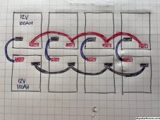
- Given my setup, 24V battery bank (400Ah 24V), FlexPower One, VFXR3524 inverter and FM 80 charge controller, does this wiring plan for the batteries look ok? I have seen wiring diagrams where the parallel wiring is created first between [2]12V batteries and then series wiring, according to my plan, I am doing the opposite. Any pros cons?
- I am thinking this way depicted below would be the best way in terms of using least amount of wire.
- Where do I run the main positive (+) and negative (-) to the FlexPower One? Off the right side of the image below?
- And what gauge wire should these mains be?
- I am planning on using 1/0 wire for all of the connections. Adequate?
Attachments
Last edited: