diy solar

diy solar

Setting up my new Solis S5 hybrid

Avier

New Member
Joined
Apr 26, 2022
Messages
22
Hello Friends,

I've finally got the FV in place.

Specs are:
x17 Longi Solar 415Wp
x1 Solis S5-EH1P3.6 K-L hybrid
x3 Pylontech US3000

As I'm starting to get the hang of how it works so a number of big and small issues are flocking.
Let's go in order:

1. Whenever I disconnect/shut down grid connection the inverter will cease all activities giving "no grid" error. At the moment all house load is connected to the AC-GRID connector. Can this be solved just by switching connector from AC-GRID to AC-BACKUP? Does the "storage mode" in advanced settings have any role in this?

2. I have a cold room in the basement (the house is a loft to the 3rd floor) and I am not sure whether it is connected to the FV system.
Let me clarify: the energy provider meter/switch is located in the basement, from it one line goes up to the house (to the main switch at whose exit the house line and inverter are connected - in parallel) and another line serves the basement.
Could it be that the cold room does actually tap into the FV but the Inverter has no way to know that? Does is have anything to do with where the CT is placed (currently in the main switch with direction toward grid - an Eastron SDM120CT)?
Actually I'm curious how the inverter is able to override grid in favour of FV and batteries.

3. I have been sold this inverter as a 6 kW thinking that it could both take and give 6 kW, but after checking the specs it seems it is not the case.

1675360626959.png1675360964115.png


So what does "Rated Output Power" 3.6 kW mean?
Does it mean that if for instance domestic load is 5 kW and the modules are producing 6 kW at full irradiation, only 3.6 kW can actually get out from the inverter; the rest has to be taken from the grid regardless and the remaining go to the battery if needed or otherwise lost to grid? I'll give it a try tomorrow..

If this is the case I have the same issue discussed here https://diysolarforum.com/threads/new-solis-inverter-setup-with-batteries.43285/, and as it was pointed out in the thread, if someone is planning to harness all the solar power produced in the morning by using a couple of aircons, oven, induction hob, dishwasher, ect., having only 3.6 kW max available makes little sense.

4. I am using Solis Cloud as remote monitoring. It gives okay charts but the update rate is ridiculous. I noticed there is another app called Solis TechView supposedly from the same company. I tried to set up an account but it doen't seem to recognize wifi data logging SN.


photo_2023-02-02_20-54-10.jpgphoto_2023-02-02_20-57-05.jpgphoto_2023-02-02_20-57-02.jpg

5. In the Inverter main screen top left corner I see the message "LmtByEPM" cyclically. Here what the manual says:


1675368278745.png

I wonder if this is just to notify that the 6.6.7 Export power Set option in the advanced settings is set to off, therefore export to grid is cut (in my case to zero). If that is the case it is okay as I set it that way for the time being.

Thank you in advance for your support!!!
 

Attachments

  • 1675360674543.png
    1675360674543.png
    109.9 KB · Views: 2
  • 1675361038550.png
    1675361038550.png
    54 KB · Views: 5
Last edited:
A lot of questions there. I'll try to answer a few of them.
Whenever I disconnect/shut down grid connection the inverter will cease all activities giving "no grid" error. At the moment all house load is connected to the AC-GRID connector. Can this be solved just by switching connector from AC-GRID to AC-BACKUP? Does the "storage mode" in advanced settings have any role in this?
The AC Backup output will stay on as long as you have sufficient solar/battery power to run it. I don't know the specs for your inverter. I suspect it can supply up to 6kW from that connector. If you do use that connector you will need a TT Earth system for it as it will not be connected to grid earth. Earth on AC Backup is tied to Neutral on that socket. Leave Storage Mode as Self use to use that output.
Could it be that the cold room does actually tap into the FV but the Inverter have no way to know that? Does is have anything to do with where the CT is placed (currently in the main switch with direction toward grid - an Eastron SDM120CT)?
The position of the CT is the important factor. It's the current flowing through that wire that the inverter uses to decide how much power to push to the AC Grid connection. Basically the CT measures the current and the meter measures the voltage. By comparing the two the inverter can work out how much is going in or out and uses that to match your house load.
So what does "Rated Output Power" 3.6 kW mean?
That's the maximum output. But you're looking at the wrong inverter. That's the 3.6kW version, the S5-EH1P3.6K-L. You need the specs for the S5-EH1P6K-L.
I am using Solis Cloud as remote monitoring. It gives okay charts but the update rate is ridiculous. I noticed there is another app called Solis TechView supposedly from the same company. I tried to set up an account but it doen't seem to recognize wifi data logging SN.
TechView is pretty useless apparently. You're pretty much stuck with the Cloud and its 5 minute snapshots unless you hook up something directly to the RS485 socket and link it to some monitoring software. There are people here who have done that.
I can't answer the question about the Export Set. Unless you have G99 approval you are limited to exporting 3.6kW to the grid and your inverter should be set up to allow that as long as you have a G98 certificate.
 
I'll try to answer some too... :)

Specs are:
x17 Longi Solar 415Wp
x1 Solis S5-EH1P3.6 K-L hybrid
x3 Pylontech US3000
Great. Where are you located? UK / Europe? (Edited to add, I see it is Sicily from your other postings)

1. Whenever I disconnect/shut down grid connection the inverter will cease all activities giving "no grid" error. At the moment all house load is connected to the AC-GRID connector. Can this be solved just by switching connector from AC-GRID to AC-BACKUP? Does the "storage mode" in advanced settings have any role in this?
That is expected for a grid tied inverter. Don't connect grid to AC-BACKUP, that will fry your inverter. Are you looking to supply power _some_ devices items from the inverter when grid goes down? If so, you'll need a separate connection for just those devices from the AC-BACKUP connection.

2. I have a cold room in the basement (the house is a loft to the 3rd floor) and I am not sure whether it is connected to the FV system.
Let me clarify: the energy provider meter/switch is located in the basement, from it one line goes up to the house (to the main switch at whose exit the house line and inverter are connected - in parallel) and another line serves the basement.
Could it be that the cold room does actually tap into the FV but the Inverter have no way to know that? Does is have anything to do with where the CT is placed (currently in the main switch with direction toward grid - an Eastron SDM120CT)?
Can you post a diagram showing the exact wiring of your setup?

Actually I'm curious how the inverter is able to override grid in favour of FV and batteries.
In simple terms, the inverter will produce a voltage fractionally higher than the grid voltage if it can supply power - this will cause the flow of electricity from the inverter to the house load, rather than from the grid.

3. I have been sold this inverter as a 6 kW thinking that it could both take and give 6 kW, but after checking the specs it seems it is not the case.
The Solis S5-EH1P3.6 K-L hybrid you mentioned above is indeed a 3.6kW inverter.

So what does "Rated Output Power" 3.6 kW mean?
Does it mean that if for instance domestic load is 5 kW and the modules are producing 6 kW at full irradiation, only 3.6 kW can actually get out from the inverter; the rest has to be taken from the grid regardless and the remaining go to the battery if needed or otherwise lost to grid? I'll give it a try tomorrow..
Yes (almost). If you are lucky to be getting 6kW from your panels, up to 3.6kWh can go to house. The remaining 2.4kW will be used to charge the Pylontechs and when they are full, the inverter will reduce the amount it draws from the panels. A 3.6kW inverter won't deliver more than that amount to the house/grid.
 
Last edited:
Earth on AC Backup is tied to Neutral on that socket.
Interesting - never knew that! Not an issue as we have TT, but seems a strange, not well documented feature.

That's the maximum output. But you're looking at the wrong inverter. That's the 3.6kW version, the S5-EH1P3.6K-L. You need the specs for the S5-EH1P6K-L.
OP says he has an S5-EH1P3.6K.

Unless you have G99 approval you are limited to exporting 3.6kW to the grid and your inverter should be set up to allow that as long as you have a G98 certificate.
FYI... OP is based in Sicily, so UK approvals not relevant.
 
Interesting - never knew that! Not an issue as we have TT, but seems a strange, not well documented feature.
Pretty sure that's why it needs a TT Earth rather than using one from the substation.
OP says he has an S5-EH1P3.6K.
Yeah. I missed that when he said it was sold as a 6kW inverter.
FYI... OP is based in Sicily, so UK approvals not relevant.
Good point. I assumed too much.
 
Thank you so much for your interest in the topic !!


I suspect it can supply up to 6kW from that connector. If you do use that connector you will need a TT Earth system for it as it will not be connected to grid earth.
Only 3 kW for EH1P3.6K-L. It makes sense. TT I guess is enough to get it from iron in the reinforced concrete pillars of the building. I believe we already arrange it in the past.

That is expected for a grid tied inverter. Don't connect grid to AC-BACKUP, that will fry your inverter. Are you looking to supply power _some_ devices items from the inverter when grid goes down? If so, you'll need a separate connection for just those devices from the AC-BACKUP connection.
I was wondering if I could connect the domestic load to both AC-GRID and AC-BACKUP each with a switch so I could in turn disconnect one or the other depending on my needs. Risky, I know. If I make a mistake, bye bye inverter. Although I could put a circuit breaker that would be triggered if I forgot to switch the opposite (would that save the inverter?).
One reason is to make sure the inverter wouldn't tap into the grid on its own, but after seeing its behavior if well configured it will tap into grid only if modules and battery are not available. Also once I switch to S5-EH1P6K-L the risk to tap into grid to offset a possible lack of power is considerable lower. Another reason is just the hassle to watch your house system going down every time the grid stop delivering, knowing that you have all the tools to avoid it.
Now that I think about it, what happens once the AC-BACKUP peaks, does the inverter cut off power?

I was also wondering if there is any way to protect inverter and batteries from lightnings? The most effective way would be to completely insulate them winch is not easy. But perhaps the most dangerous source is AC-GRID. With that gone the only way for a lightning to break through would be from the modules wiring, much less likely to happen. Another source for unwanted backflow could be a faulty TT.

Leave Storage Mode as Self use to use that output.
So when to use the off grid mode? Just curious


The position of the CT is the important factor. It's the current flowing through that wire that the inverter uses to decide how much power to push to the AC Grid connection. Basically the CT measures the current and the meter measures the voltage. By comparing the two the inverter can work out how much is going in or out and uses that to match your house load.
In simple terms, the inverter will produce a voltage fractionally higher than the grid voltage if it can supply power - this will cause the flow of electricity from the inverter to the house load, rather than from the grid.
I see. Very interesting! So simple and yet genius. Of course a higher voltage would take "priority" (being pushed in) over a lower one.
Therefore if I bring the CT all the way down to the basement node the inverter would detect the load and supply power!?

Can you post a diagram showing the exact wiring of your setup?
Last time I drew something like this was in school - the CT is placed past the main switch although it doesn't seem to make a lot of difference.


photo_2023-02-03_22-57-14.jpg

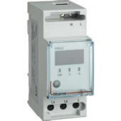
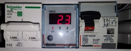
R is a management relay I installed some years ago to monitor house consumption is a bticino F80CG (similar to Eastron). Very useful!

g1vg798u.png

The ideal would be if I could monitor cold room consumption from R (that way I have everything under control - the Eastron is outside along with the inverter), but it seems to do that I need to lay two more wires down to the basement.
I still can't understand where the CT has to be placed for the inverter to power the cold room.


That's the 3.6kW version, the S5-EH1P3.6K-L. You need the specs for the S5-EH1P6K-L.
The Solis S5-EH1P3.6 K-L hybrid you mentioned above is indeed a 3.6kW inverter.

I just had a call with the dealer asking if I could change the S5-EH1P3.6K-L for a S5-EH1P6K-L and we found out that I was meant to have the S5-EH1P6K-L rather than the 3.6. So, I guess this should be solved.
Yes, S5-EH1P3.6K-L can handle 5.7kW suggested FV power (today mine reached 5.5 kW at 10 am) but only output 3.6 kW max toward AC-GRID and around 3.4 kW max to batteries. Wonder how much kW from FV it can withstand.

Hope he hasn't paid for a 6kW one :eek: but maybe he just got the number wrong when checking it ?
Apparently yes. We realized that EH1P3.6K is a bit misleading, it makes you thing the model is a EH1P3 6KW. That's probably why they made a mistake. I fell for that too.

hook up something directly to the RS485 socket and link it to some monitoring software. There are people here who have done that.
I've read something about it but atm it seems out of my league
Yeah no G99 in Italy. Probably something similar.
 
Last edited:
1. Whenever I disconnect/shut down grid connection the inverter will cease all activities giving "no grid" error.
That's normal, and mandated by law, you don't want to keep injecting power into the grid when it's down as that would electrocute the buys who come to fix your power. That said it should not "cease all activities": when the grid is down it will still charge the batteries (if they're not full) and output power on the backup port.

At the moment all house load is connected to the AC-GRID connector. Can this be solved just by switching connector from AC-GRID to AC-BACKUP? Does the "storage mode" in advanced settings have any role in this?
No you shouldn't put your whole house on the backup port. Because if you have a blackout, you'll want to power a few important things like your freezer. If the weather is bad for solar, grey, overcast, your 17 panels will produce enough power for a few hundred watts backup load indefinitely. But if you connect the whole house, all the appliances that suck power all the time will just drain your battery very quickly. So if you want to use the backup functionality, you should at least put a socket on the backup port and run an extension cord to your freezer. Next you can install some wiring to supply the critical loads when you have time. It's a good idea to put a transfer switch, to keep the loads powered if the inverter breaks down...

Does is have anything to do with where the CT is placed (currently in the main switch with direction toward grid - an Eastron SDM120CT)?
Actually I'm curious how the inverter is able to override grid in favour of FV and batteries.
It's simple:

Since you wired the Eastron meter in grid mode, it measures the total net power used by the house plus the inverter.
The inverter talks to the meter and injects the right amount of power via its grid port to bring the power value measured by the meter to zero.

So say your house is using 300W, we use a positive sign for consumed power, so +300W.
The inverter is injecting 300W, we use a negative sign because this power goes in the other direction, so -300W.
Meter measures the total, +300-300=0, the inverter is happy, it keeps injecting 300W.

Now you turn on your toaster, which draws 1000W. The house now uses 1300W total (300W as before + 1000W toaster). The inverter is still injecting -300W. So the meter now measures 1000W instead of zero, and sends this number to the inverter.
The inverter notices metered power increased by 1000W, so it increases its injection power by the same value to compensate. This takes a few seconds, but in the end, the house is using +1300W, the inverter power is -1300W, and the meter measures zero again.

If any load is connected on the grid side of the meter, the meter won't measure it, it only measures power on the load side. So if you connected something on the grid side of the meter, the inverter will never hear about it and it won't do anything about it.


3. I have been sold this inverter as a 6 kW thinking that it could both take and give 6 kW, but after checking the specs it seems it is not the case.

Well that's marketing!

It's a 3.6kW inverter on the grid side. HOWEVER it can input about 6kW solar, then output 3.6kW on the grid and store the rest in the batteries. So if there's a lot of sun and you max out the 3.6kW output, it will still charge your batteries. If it was limited to 3.6kW on the solar side, it wouldn't do that.

My EH1P-6k does the same, it can input about 8-9 kW solar, max out the grid output at 6kW, and still charge the batteries with the rest. So it's not a problem if you have a bit too many panels.

So what does "Rated Output Power" 3.6 kW mean?
Does it mean that if for instance domestic load is 5 kW and the modules are producing 6 kW at full irradiation, only 3.6 kW can actually get out from the inverter; the rest has to be taken from the grid regardless and the remaining go to the battery if needed
Yes
or otherwise lost to grid? I'll give it a try tomorrow..
Not "lost", the power that it cannot use is not produced. PV panels do not produce if the inverter does not pull the power from them.
I wonder if this is just to notify that the 6.6.7 Export power Set option in the advanced settings is set to off, therefore export to grid is cut (in my case to zero). If that is the case it is okay as I set it that way for the time being.
Yes it's okay.
EPM is the internal power manager.
LimitByEPM means it's restricting its output power to what your house is using, and will charge the batteries with the rest. If this is what you want then it's fine. If you sell your electricity to the grid you could use another mode which prioritizes export.

> I was wondering if I could connect the domestic load to both AC-GRID and AC-BACKUP each with a switch so I could in turn disconnect one or the other depending on my needs.

When grid is available, Grid and Backup ports are connected internally with a relay, so that wouldn't be useful. It measures current on both separately though.
 
Thank you @peufeu for your contribute. I've read some of your tweaks on your threads. Great job!

That's normal, and mandated by law, you don't want to keep injecting power into the grid when it's down as that would electrocute the buys who come to fix your power. That said it should not "cease all activities": when the grid is down it will still charge the batteries (if they're not full) and output power on the backup port.
It makes perfectly sense and it should not be otherwise.

No you shouldn't put your whole house on the backup port. Because...It's a good idea to put a transfer switch, to keep the loads powered if the inverter breaks down...
I agree. Although my domestic consumption is pretty straightforward, just fridges. Boilers are under timer switch. Other than that there is always around 30-40 W from standby appliances and phone chargers. The way the inverter is placed is difficult to lay extension or split the electric implant.

When you talk about transfer switch you mean to keep the loads connected directly to grid if the inverter malfunctions?

If any load is connected on the grid side of the meter, the meter won't measure it, it only measures power on the load side. So if you connected something on the grid side of the meter, the inverter will never hear about it and it won't do anything about it.
So it actually makes all the difference. If I want the inverter to supply the basement I then have to take the CT all the way down to the node before grid energy meter.

My EH1P-6k does the same, it can input about 8-9 kW solar, max out the grid output at 6kW, and still charge the batteries with the rest. So it's not a problem if you have a bit too many panels
I'll soon get it replaced with the same one. 3.6 kW are pointless with my size of FV and domestic consumption. Do you know how much the EH1P-6K can input max in the batteries? The EH1P3.6K tops at 3.4 kW, will the EH1P6K reach close to 6 kW?

When grid is available, Grid and Backup ports are connected internally with a relay
That means when grid is available it does not matter where the load is connected whether if AC-GRID or AC-BACKUP.

Now going back to what you accomplished in your thread I began to get lost as soon as you started to talk about connecting the USB-RS485, reverse engineering, phyton, etc. :ROFLMAO: Do you think you will ever make a guide on how to obtain quick monitoring info than the 5 min SolisCloud snapshots?
 
When you talk about transfer switch you mean to keep the loads connected directly to grid if the inverter malfunctions?
Yes. If you turn off the inverter, the backup output also shuts down.
Solis does the right thing with neutral:
- in on-grid mode, backup output is just connected to grid port,
- in off-grid backup mode, backup port neutral is connected to Earth internally.
So if you put a GFCI/RCD on the backup output, it will work. This may be mandated by code. Here (France) code also mandates a special snowflake horribly expensive RCD type B before hybrid inverters... got it for €250 second hand :ROFLMAO:

Also a transfer switch is nice to avoid cutting power to the house when fiddling with the inverter...

So it actually makes all the difference. If I want the inverter to supply the basement I then have to take the CT all the way down to the node before grid energy meter.
Exactly.
Do you know how much the EH1P-6K can input max in the batteries? The EH1P3.6K tops at 3.4 kW, will the EH1P6K reach close to 6 kW?
Max 100A on the 48V port, so 4.8-5kW.
Battery sets maximum charge current via CAN port and reduces it when close to full charge.
That means when grid is available it does not matter where the load is connected whether if AC-GRID or AC-BACKUP.
Yes
Now going back to what you accomplished in your thread I began to get lost as soon as you started to talk about connecting the USB-RS485, reverse engineering, phyton, etc. :ROFLMAO: Do you think you will ever make a guide on how to obtain quick monitoring info than the 5 min SolisCloud snapshots?
It depends: there are several ways to get data
- Crummy cloud app
- No programming: use something like home assistant. I hear it's nice, but it kinda has the same problems as "smart" devices, it will do what it wants, not necessarily what you want
- With programming: in this case getting data from the inverter isn't difficult, the complex part is putting it in a database, plotting, etc. It's the most flexible approach but of course it requires programming.
 
So if you put a GFCI/RCD on the backup output, it will work.
I think the one I currently have placed before the house should do. Does it?

photo_2023-02-03_22-57-14.jpg
What I referred to as magnetothermic are RCDs. The main switch is actually a MCB which you see below along with R and House RCD:

photo_2023-02-10_20-59-16.jpg

Also a transfer switch is nice to avoid cutting power to the house when fiddling with the inverter...
Definitely a good idea to add a transfer switch

Max 100A on the 48V port, so 4.8-5kW.
That's much better

It depends: there are several ways to get data
I need to do more research. I know little about it

If you do use that connector you will need a TT Earth system for it as it will not be connected to grid earth.
I have checked and yes we have TT. What do you mean by "grid earth"?
 
Last edited:
What I referred to as magnetothermic are RCDs. The main switch is actually a MCB which you see below along with R and House RCD:
OK the one on the right of the pic is GFCI/RDC with 30mA ground fault trip current.

I think the one I currently have place before the house should do. Does it?
It's on the grid port side of the inverter, right?
In this case, it will protect against a ground fault in the inverter, or in other appliances on the grid side of the inverter.
If an appliance connected to the inverter backup port has a ground fault, and grid is available, this will trip this RCD since the inverter connects grid and backup internally.
However the inverter will detect this as a loss of grid/blackout, and it will do its job powering the backup output.
This means the RCD on the grid side of the inverter doesn't protect you against getting zapped by ground faults on the backup side. To be protected you need another RCD on the backup output.

I have checked and yes we have TT. What do you mean by "grid earth"?
RCD's don't actually detect ground faults, they measure the difference in current between live and neutral. In TT mode, grid neutral is tied to earth at the utility transformer. If there is a ground fault in an appliance, current will flow from live to earth in the appliance. So the RCD will detect that not all the current that flows in the live wire returns through the neutral wire, the difference is current leaking to Earth in the faulty appliance. If this is higher than 30mA it will cause your RCD to trip and prevent you from getting zapped.

When the inverter is in backup mode without grid, it is completely isolated from the grid. So if an appliance has a current path from live to earthed chassis, no current will flow because there is no complete path for it to flow through earth, so the RCD will not trip and the dangerous condition will go unnoticed. That's why in backup mode, the inverter connects neutral to earth internally, like the utility transformer does. That creates a path for the fault current, and so the RCD you install on the backup output will trip if there's a fault.

This also means you need a two pole transfer switch, to make sure both poles from the backup output are isolated from the grid when they need to. I used a DPDT contactor for this, with the coil powered by the backup output. So if the inverter is off, the relay is off, and backup loads are powered from the grid. If the backup output is on, the relay is on, and backup loads are powered from backup output. You can use a manual transfer switch too, but you can't use two switches, because if they're both on at the same time then the backup output will be connected to the grid and that will probably damage the inverter.
 
Today we replaced the EH1P3.6K with EH1P6K. And take the CT down to the basement node. A satisfying job and a totally different level!

you can't use two switches, because if they're both on at the same time then the backup output will be connected to the grid and that will probably damage the inverter.
indeed the two switches is a rough solution. A DPDT (even a relay type) would be perfect !
Given how my implant is structured it would be too complicated to split it. It's all or nothing on the backup port.

I was checking if the Eastron SDM120CT has a real-time power monitoring function but I can't find it? Does it have it?
 
Last edited:
After having monitored the empty cold room (1.5 kWh at 5°C ) for two days I realized that the batteries (x 3 Pylontech US3000) are just enough to keep the system running until the modules start producing again in the morning. I can also indulge in turning the air conditioner on for a couple of hours or so and also bake a cake. Doing so I end up with around a bit less than 20% charge left in the morning.
I imagine a slightly more demanding condition at summer time with a full cold room - notwithstanding the chilling stage always be at day time. For this reason I am torn between taking another battery to enlarge the storage capacity or put a timer switch at night time in the cold room and use the day time to bring the room at temperature. A timer costs 30 euro while another battery more that a thousand...

Maybe waiting sometime to see whether the prices go down a bit. I suppose it not possible to side some lead-acid with li-fe-po...?

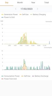
You can clearly see when the cold room motor is on

photo_2023-02-19_23-15-27.jpg
 
Last edited:
I was checking if the Eastron SDM120CT has a real-time power monitoring function but I can't find it? Does it have it?
What do you mean by real time power monitoring?
It has a modbus port, that's used by the inverter to read the power used. It's possible to spy on this data, but when the inverter is running it will read close to zero watts, so it's not useful. With a modbus interface it's possible to query the inverter using the COM port and read all the information.

If your cold room does too many on/off cycles you could try putting some water jugs as thermal mass.

Maybe you can find a thermostat with day/night temperature settings (or two thermostats and a clock) to set it to a colder temperature during the day, so it runs less at night...
 
What do you mean by real time power monitoring?
I was looking to something like the bticino F80CG. It gives the real time consumption up to 6.5 kW.

If your cold room does too many on/off cycles you could try putting some water jugs as thermal mass.
You mean to keep some water tanks full of water inside. Good idea, I am going to try it.

Maybe you can find a thermostat with day/night temperature settings (or two thermostats and a clock) to set it to a colder temperature during the day, so it runs less at night...
I was thinking to set it close to 0°C and then put a timer switch to keep it off part or most of the night. I will try with the water tanks and see how high the temp goes at night if I keep it off.
 
If you want to know how much power the house is using when the inverter is running, you have to add power generated by the inverter and power drawn from grid measured by the meter. The inverter also gives this information over modbus on the COM port.
 
f you want to know how much power the house is using when the inverter is running, you have to add power generated by the inverter and power drawn from grid measured by the meter. The inverter also gives this information over modbus on the COM port.
Add where?

Also, will choosing the meter placement, whether on grid or load, make any difference in the way the inverter respond to power demand and consumption?
 
Add where?
If:
- the house is using 1000W
- the inverter is only producing 500W
- remaining 500W are taken from grid

In order to measure the power used by the house (1000W),

If the meter is on "load" side it measures power used by the house, so it gives the value directly.

If the meter is on "grid" side it only measures power drawn from grid (500W) which is not the power used by the house. The inverter adds (as in, it makes an addition) its own output power (500W) to get the actual power value used by the house (1000W).

Also, will choosing the meter placement, whether on grid or load, make any difference in the way the inverter respond to power demand and consumption?

The inverter reacts a bit faster (a few seconds) with the meter on load side, but besides that, you should use the one that's most convenient for wiring.
 
If the meter is on "grid" side it only measures power drawn from grid (500W) which is not the power used by the house. The inverter adds (as in, it makes an addition) its own output power (500W) to get the actual power value used by the house (1000W).
In that case it is on the load side, which is what I am most interested into.

Thank you so much @peufeu for all your tips end explanation ?
 
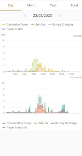
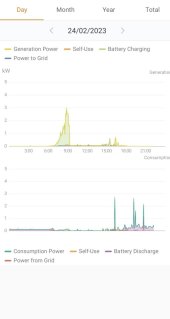
Today I had a curious chart

photo_2023-02-23_20-28-22.jpg
For some reason the inverter chose to tap into grid instead of using the battery, splitting Consumption Power in half (overlapped in the chart) between Self-Use and Power from Grid. Why not using battery first?
I have optimal income set to "stop", but I had also backup mode set to off. Perhaps the latter had to be set to on. Even though, self-use mode should prioritize battery over grid..
 
For some reason I had to set "optimal income" to on...

I tried as well but it still taps into grid. I wonder why. It happens during the day, not in the afternoon, I don't know exactly when. It was working fine until a couple of days ago.

Yesterday, without knowing I placed the CT in what I later realized to be the line that served the basement only, leaving the house line out. that is the result (until I realized what I did at 3 pm and change it to house line).

photo_2023-02-24_22-18-26.jpg

Obviously in the basement everything was off, so aside from battery charging everything was taken from grid. Here I might have guessed the why of the CT direction (the arrow is toward grid), although I do not quite understand it completely. What happen if the CT direction (currently toward grid) is set toward load?

Another change that might have triggered the aforementioned grid-tapping behavior was to set meter placement setting to load instead of grid. I thought on load it would give a better reading. It seems it is not the case.
Also, perhaps if I set the meter placement setting to load, then I have to reverse the CT arrow which has always been toward grid. Wonder if that is what might have not gone down well with the inverter.

Now I went back to initial configuration, with
1. CT placed around both lines (house + basement)
2. meter placement setting set to grid
3. optimal income set to "stop"

Let's see what happen tomorrow
 
Last edited:
Everything seems to be back to normal.
I think the meter placement setting has to be paired with CT arrow direction. If the two don't match the inverter doesn't respond as it should.
 
Everything seems to be back to normal.
I think the meter placement setting has to be paired with CT arrow direction. If the two don't match the inverter doesn't respond as it should.
That's correct. If they don't match then the inverter will think exports are imports and imports are exports and fight against them.
 

diy solar

diy solar
Back
Top