diy solar

diy solar

Sending Solis S5 Inverter grid import/export from Home Assistant

andypnz

New Member
Joined
Mar 27, 2024
Messages
8
Location
New Zealand
I have a Solis S5 S5-GR1P(3-6)K 5kW inverter. It is a ‘meter’ type - not CT type.

I want to use export limiting. But rather than buy a separate power meter to feed ?modbus to the meter port on the inverter, I would like to use grid import/export data I already have within Home Assistant. Can I use ESPHome on an esp8266 + serial-modbus adaptor to feed this value to the Solis S5?

Any help appreciated! I am not even sure the ‘meter’ port on the inverter accepts modbus?
 
Last edited:
Welcome!

I suspect the S5-GR1P uses similar technology to the hybrid S5 Solis versions that I have (RHI and EH1P models). If so, then yes, the power meter port is Modbus RTU over RS485.

If so, then suggest your first port-of-call is this thread below, in particular @peufeu's Grugbus project detailed on page 2 of the thread, where the code he publishes allows full control of the Solis inverter by intercepting and manipulating the Solis power meter data. As you will see it is also possible to read and write from the Solis comms port to control various settings - the only caveat being not to write too frequently to values that are preserved in flash memory or you could wear out the flash storage.

 
I want to use export limiting. But rather than buy a separate power meter to feed modbus to the meter port on the inverter, I would like to use grid import/export data I already have within Home Assistant. Can I use ESPHome on an esp8266 + serial-modbus adaptor to feed this value to the Solis S5?
If the goal is to save money by not buying a meter, it's probably not worth it.

If it's like mine, it'll check the meter every second. I don't know if home assistant can be fast enough to poll the meter often enough and forward the data to your modbus wifi interface.
 
Thank you...
The goal is not to save money - but to get the grid data to my inverter is going to require a wireless link (purely from a logistics / cabling point of view) ... I already have the grid import / export data in HA (1Hz is no issue) and am sending that out over MQTT (again at 1Hz)...
So the final bit of the puzzle is to collect the MQTT data, and output it emulating an acr10rd16te or ddsd1352-c meter. I found some Arduino code which will grab the MQTT data and output as SDM230 (not accepted by the Solis inverter) https://github.com/alessandromatera/SDM230-emulator-growatt-esp-mqtt
The other option would be to try and do this using ESPHome (HA - ESPHome device - RS-485 - Solis inverter).
Note that I am using the inverter 'Meter' RS485 port... The other data port (for the WiFi dongle) I am using to get inverter data into HA....

@peufeu I see you used a SDM120 and SDM630 - does your inverter have a setting for this meter? My Solis only has settings to use acr10rd16te or ddsd1352-c. I wonder if the Arduino code I have grabbed has an issue or maybe a hardware config issue....
 
Last edited:
So the final bit of the puzzle is to collect the MQTT data, and output it emulating an acr10rd16te or ddsd1352-c meter.
Yes

Whether you do it with ESP32 or a Pi, your choice, both can do it. I used an orange pi lite because it's cheap, low power (1W) and runs python.

Note that I am using the inverter 'Meter' RS485 port...
Correct, the inverter will be modbus master and your device must act as modbus slave.

I see you used a SDM120 and SDM630 - does your inverter have a setting for this meter?
Currently it's emulating what Solis calls "Acrel 1 phase meter", here's the register list, which I reverse engineered from the inverter's modbus requests. I also have the register list for ACR10R which is completely different and did not work. I guess maybe Solis uses a custom version of this Acrel meter with different registers from the stock one.
 
My Solis inverter has two meter choices... acr10rd16te or ddsd1352-c. I have set it to acr10rd16te. On the RS485 meter-port I understand the Solis acts as master and the smart meter (my esp8266) is the slave.

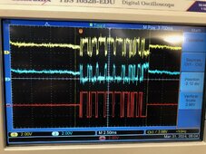
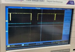
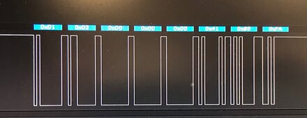
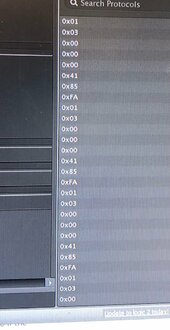
I have confirmed the inverter is sending out what I guess is a Modbus request (pic attached). And the TTL-RS485 converter is sending serial data to my ESP8266 (pic), and my analyser shows this as repeating serial data (pic). Does that look ok so far?

My ESP8266 is not responding to these requests (not sending out any serial data). So my next step is to get the ESP8266 to send something out on its serial Tx, and then see this on the Modbus...... This https://github.com/alessandromatera/SDM230-emulator-growatt-esp-mqtt code is (I guess) not working as it is looking for a Growatt inverter Modbus request code check sum (calc_crc)... Any suggestions how you would change this code to respond to the data request seen in my pictures?

Once I have some response from the esp8266 I will then figure out what needs to be in that response :)

Thank you for any assistance....
 

Attachments

  • IMG_7739.jpg
    IMG_7739.jpg
    323.1 KB · Views: 1
  • IMG_7740.jpg
    IMG_7740.jpg
    256 KB · Views: 0
  • IMG_7741.jpg
    IMG_7741.jpg
    150.5 KB · Views: 1
  • IMG_7742.jpg
    IMG_7742.jpg
    132.3 KB · Views: 0
the Solis acts as master and the smart meter (my esp8266) is the slave.
Yes
I have confirmed the inverter is sending out what I guess is a Modbus request (pic attached). And the TTL-RS485 converter is sending serial data to my ESP8266 (pic), and my analyser shows this as repeating serial data (pic). Does that look ok so far?
Yes
Modbus is a simple protocol. If you look at received bytes you can decode it manually.

My ESP8266 is not responding to these requests (not sending out any serial data). So my next step is to get the ESP8266 to send something out on its serial Tx, and then see this on the Modbus......
Yes you have to implement modbus slave.

You don't have to write the code from scratch, there are tons of modbus libraries, here's a random one : https://github.com/emelianov/modbus-esp8266 it even has an example for a modbus master https://github.com/emelianov/modbus-esp8266/blob/master/examples/RTU/slave/slave.ino

I did not look into this library so can't vouch for it, as I'm using pymodbus with python.


code is (I guess) not working as it is looking for a Growatt inverter Modbus request code check sum (calc_crc)... Any suggestions how you would change this code to respond to the data request seen in my pictures?
The CRC is part of modbus protocol, it is not specific to any brand or product.

My suggestions are:

- read up on modbus protocol
- use a modbus library that works, don't implement it from scratch, it's a waste of time
- don't use software serial, use a real UART instead.
 
Well, I got the thing sending some response on Modbus.... but of course not the response the inverter is requiring.

I am not really clear what the minimum response expected by the inverter is?

30945 130004185FA process register read 1 3 0 65
gridpower: 56.00
response 2 4 4 42 60 0 0 DC E2
31281 130004185FA process register read 1 3 0 65
gridpower: 56.00
response 2 4 4 42 60 0 0 DC E2
31584 130004185FA process register read 1 3 0 65
gridpower: 56.00

Thanks for your help.... I will order a RPi Orange Lite.... sounds like an easier way forward.....
 
What the hell does "130004185FA" mean...

If it was 01 03 00 00 00 41 85 FA it would mean:
01 slave address
03 read register
00 00 address of first register to read
00 41 number of registers to read

I am not really clear what the minimum response expected by the inverter is?

Well it expects a modbus response with the registers it requested. The response quoted above has the wrong slave address, wrong function code, didn't check the CRC, and it contains 2 registers instead of the requested number so yeah it's not going to work. Much simpler to use a modbus library which will build the responses for you, all you got to do is tell it what registers you have and put values in them.

For the "minimum" part, the only register value it's using is active power. All the others (voltage, energy, etc) are just to display on the inverter front panel. Maybe it checks the values, who knows, but you can put dummy stuff there, maybe it'll work with all zeros except active power which must be correct.
 
Thank you... still getting my head around this... and sorry, leading zeros were truncated.....

The inverter sends this request:
Rec Buffer: 01 03 00 00 00 41 85 FA host address: 01 function code: 03 start address: 00 00 number of registers: 00 41 checksum: 85 FA

Would you be kind enough to let me know a valid response to this request (in hex)? That would be really helpful and get me started....
 
Here's the register list for what my inverter calls "Acrel 1 phase".


Type is in the "Type" column (U16 means unsigned 16 bit int, etc)

So if the inverter requests 0x41 (65) registers starting at address 0 you have to send 65 16-bit values (130 bytes) with all the values in the correct spots. So you can make a "uint16 regs[65]", do regs[13]=power, fill the others too, and send the whole array. Maybe you have to swap byte order, it depends on what the byte order of ESP32 is.

Or use a modbus library which will do that for you, including the header and CRC, it's much simpler.
 
Thank you @peufeu for your help....

My Solis S5 is happy (no failsafe) with the data I am sending :) I now just need to start playing with values to confirm the active power position in the data - then start using the actual grid power rather than fake data.... But first need to figure out where in the Solis menu I can view the values it is recieving.....

Rec Buffer: 01 03 00 00 00 41 85 FA HostAdr: 01 FnCode: 03 StartAdr: 00 WordSize: 65
gridpower: 272.00
response 01 03 82 00 00 00 01 00 02 00 03 00 04 00 FF 00 06 00 07 00 08 00 09 00 0A 00 0B 00 0C 00 0D 00 0E 00 0F 00 10 00 11 00 12 00 13 00 14 00 15 00 16 00 17 00 18 00 19 00 1A 00 1B 00 1C 00 1D 00 1E 00 1F 00 20 00 21 00 22 00 23 00 24 00 25 00 26 00 27 00 28 00 29 00 2A 00 2B 00 2C 00 2D 00 2E 00 2F 00 30 00 31 00 32 00 33 00 34 00 35 00 36 00 37 00 38 00 39 00 3A 00 3B 00 3C 00 3D 00 3E 00 3F 00 40 9F 03
 
If it does not trigger failsafe it means the modbus response has the correct form (length, crc, etc) so that's good. All that's missing is to put the correct values in the proper slots.

Your byte order seems correct: 0x1234 should be sent as 0x12 34

I don't know about your inverter, but on mine, I did it like the modbus response above implies: I set each register value equal to the address (ie, send 00 00 00 01 00 02 etc) then looked what showed up on the display. Note some registers are not in integer units, in my link above there is a "Unit" column, for example it is 0.1V for voltage. That means if the register contains 2345 the actual voltage is 234.5.

If it displays gibberish, maybe it wants a 32 bit value, or a float.
 
Sending this (0x01, 0xF4) results in 5.0kWh on the soils display. I presume this positive number represents grid export?

response 01 03 82 00 00 00 00 00 00 00 00 00 00 00 00 00 00 00 00 00 00 00 00 00 00 00 00 00 00 00 00 00 00 00 00 00 00 00 00 00 00 00 00 00 00 00 00 00 00 00 00 00 00 00 00 00 00 00 00 00 00 00 00 00 00 00 00 00 00 00 00 00 00 00 00 00 00 00 00 00 00 00 00 00 00 00 00 00 00 00 00 00 00 00 00 00 00 00 00 00 00 00 00 00 00 00 00 00 00 00 00 00 00 00 00 00 00 00 00 00 00 00 00 00 00 00 00 00 00 01 F4 00 00 F9 45

Out of interest, should I be able to send the inverter negative numbers (to represent grid import)? Or is only export displayed (which is what we are interested in)?

Also, would you have time to let me know appropriate inverter settings for 1kWh export limitation? Including what you would use for the soft and hard limits? And should these be +ve or -ve for 1kWh export limitation....
 
Last edited:
I don't have this inverter, I have the S5-EH1P hybrid, so I don't know how yours will behave exactly, but the setting is probably called "backflow power".

Now did you mean power (in watts) or energy (in kWh)?

> should I be able to send the inverter negative numbers (to represent grid import)? Or is only export displayed (which is what we are interested in)?

Yes, it's signed. I don't know how it will display it...
 
Ok.. some progress... Firstly, I was populating "export power energy (kWh)" - which was the wrong field.... The word 'power' had me thinking this was it.....

I am now populating Export_P. The other relevant field I can look at (and populate if required) is Export_I. There is no display of Export_V on my inverter, but can blindly populate the fields if required.

A couple of questions:
1. When I look at 'Export_P' on the inverter, should this be +ve or -ve for export?
2. In the inverter Internal EPM setup - 'soft backflow power' - should this be +ve or -ve to limit grid export to say 2000W export?
3. What should 'hard backflow power' be set to? And I guess hard limit can remain off?

Thank you again for all your help!
 
1. When I look at 'Export_P' on the inverter, should this be +ve or -ve for export?
I don't know, the settings are different on mine...

If the settings are correct then it will work and limit export as you expect ; if the sign is incorrect it will either always go full power or zero.
 
Back
Top