diy solar

diy solar

Sizing an array for MPP Solar LV2424

Because SCCs are generally very efficient devices e.g. 95-98%, it is always the output FETs that determines the maximum PV input power. FETs always have a voltage drop across them to operate (as all semi-conductors do) so when current flows through them, power loss is inevitable. This power loss is expressed as heat, hence the large heat-sinks on high-power SCCs. There is only a finite amount of heat that can be dissipated, so SCCs have a limit to the current they can supply.

Exceeding the input PV power specification could potentially lead to excessive current flow into the battery, which in turn will heat the FETs beyond tolerance and potentially cause a cascade FET failure (many FETs are usually wired in parallel, so if one FET fails, the others take on the load, which in turn puts them at higher risk of failure - there is always a 'weakest link' when it comes to parallel FETs). It is very unlikely that input current would be anywhere near output current, due to the relatively higher voltage of PV arrays.

I don't know the impact of excessive voltage but I'm guessing this will be due to component tolerances, such as the dialectic breakdown specification of capacitors etc.

I know that it may sound 'conformist', but I would just advise not exceeding either the maximum PV power or maximum PV voltage specifications!

I'll also bet my own money that a manufacturer 'know' that there products have been used outside of specification when it comes to warranty claims - they're not stupid.

Definitely agree with the comments about having as higher voltage on PV input as possible, within specification, obviously!
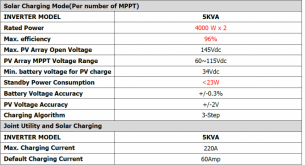
You can configure maximum charging from 10A to 140A, though only 80A can come from solar; the rest from utility. So, setting aside maximum specifications, if I set it to 10A, where does the rest of the power coming in through PV go?

It has the ability to direct PV also to load. So, assume no load with 10A limit on battery charging, and 60A coming in through PV. How could the inverter deal with the remaining 50A? The answer to this question is likely the answer to how it could deal with over 80A.

1585406139359.png
 
I don't know the impact of excessive voltage but I'm guessing this will be due to component tolerances, such as the dialectic breakdown specification of capacitors etc.

The first limit you hit is most likely the FETs breakdown voltage (high voltage fets are expensive...), even 1 V above can kill them. Caps and co would be fine even with a few V above the rating (but not on the long term of course).
 
So, setting aside maximum specifications, if I set it to 10A, where does the rest of the power coming in through PV go?
An interesting question but I think the underlying premise for it is incorrect. You make it sound like there is a 'bucket of Watts' that has to go somewhere but if you consider a battery, that too can be thought of as a 'bucket of Watts' but current only ever flows from it per Ohm's Law. For example, with a 25,000W PV array at 150Voc, only 500mA would flow if the SCC represented a 300Ω resistance to it.

I remember reading a while back that MPPT SCCs effectively represents a variable load to the PV array, that's how they identify and track the MPP. Can't remember the details right now, but I suspect this same mechanism is used to limit the charge current.
I've heard that explanation for an open circuit related question. But, haven't heard that, yet, for a closed circuit. Can't just compare PV to a battery, as it does not store energy. Not ruling your explanation out. Just saying it needs more color, perhaps on how PV production works.
 
Why is there a "Range" on an MPPT?

The MPPT gets the maximum watts no matter what. The range is there to support cold weather. The colder the weather the higher the volts.

As per Midnite solar, the less voltage you have on an MPPT the more efficient it is.

Volts times Amps always equals Watts. (squished by resistance) The fattest cable the better.

On any MPPT aim for the VOC to be the center of the voltage range unless you never see cold weather.

I have my MPP Solar (LV5048s) set to 10 amps AC and 160 amps max total. I will never see that much. As my batteries get fully charged, just like any other charger the amperage gets less and less. The MPPT basically turns off the solar panels. If I want to use that excess solar, all I have to do is use whatever I want on the AC output side of MPP Solar. Today is a pretty freaking awesome solar day. My batteries are fully charged, and I am charging my Chevy Bolt. (At 10 amps AC)
 
The MPPT basically turns off the solar panels.
So you are saying it opens the PV circuit? You have any idea the frequency it does this. Is there data in the output (software) that shows this?

Have you noticed temps rising? If so, under what conditions?

I haven't noticed temps rising on my LV2424, but haven't put a lot of load on it... just 500W continuous on sunny days.
 
As per Midnite solar, the less voltage you have on an MPPT the more efficient it is.
I dare say that this is correct, I'm not an expert on the internal electronics of SCCs, but I'm guessing the efficiency gain reaped from having a lower PV voltage pales into insignificance when considering the power transfer efficiency of higher voltage PV. Power losses through copper cable is proportional to the square of the current flowing through it and, over relatively long distances, these losses can become significant i.e. 100's of Watts. I'm guessing the internal efficiency of an MPPT probably doesn't vary much from the rated efficiency e.g. 98 - 99%.

I would always recommend having a high as possible voltage on the PV side of an MPPT, within the specs of the SCC, obviously.
Why is there a "Range" on an MPPT?
To accommodate a variety of different PV panels. One 100W panel might have a Vmp of 19V, another it might be 26V, depending on how it is constructed. The range is there to inform consumers that the SCC will function i.e. charge the battery, within this Vmp range. Both Voc and Vmp specifications are important, albeit for different reasons.
So you are saying it opens the PV circuit? You have any idea the frequency it does this. Is there data in the output (software) that shows this?
An MPPT SCC does not switch the output on/off like a PWM SCC does. The output will either be entirely switched off i.e. array Voc < SCC operational voltage (e.g. 14.4V + 5V) or will be continuously varying multiple of times per second as it tracks the MPP of the connected array.
 
So you are saying it opens the PV circuit? You have any idea the frequency it does this. Is there data in the output (software) that shows this?

Have you noticed temps rising? If so, under what conditions?

I haven't noticed temps rising on my LV2424, but haven't put a lot of load on it... just 500W continuous on sunny days.
As the battery gets full, just like any other charger the amp "draw" gets less and less.

Unlike Grid-tied setup, there is no place for the current to go. There is just no place for the "current" to dump. It's not like a wind turbine with a dump load, it just opens the circuit, and doesn't collect the energy.

I would always recommend having a high as possible voltage on the PV side of an MPPT, within the specs of the SCC, obviously.
I used to think that until I read what Midnite Solar puts out. So I figured, they have been doing this a lot longer than I have. Why go against their knowledge and experience? ?
 
I do agree with that, though I guess it does depend on the SCC.

They are all pretty similar so you should expect roughly the same efficiency curves shapes.

They are usually DC/DC buck converters so the higher the delta between Vin and Vout the higher the losses.
 
Love some of the answers, some very knowledge people in this forum.

As my understanding, the short version:
- In MPPT chargers, you can oversize the PV array, however this should be done between certain limits, as the over wattage can cause the electronics to run hotter, which can cause decrease in the lifespan or failures.
- Good quality chargers might support more watts than rated, however we are not very sure of the quality of Chinese inverters, so the safer route would be to stay between specs.

In my case, i will stay under the 2000W limits as for my case the reliability its more important than getting up to the last watt of efficiency. Also ive seen a lot of videos of burned LV2424's and other MPP Solar equipment, and i suspect that some of those failures might be because of people running them at near the rated value (or over.).. cheap electronics dont seem to have high security margins so IMO its better to run them underated.
Midnite Solar states a lower voltage is more efficient. There is no reason to max out the volt range with ANY MPPT.

Think of an MPPT as a variable dimmer switch for an incandescent light.
Think of a PWM as a dimmer switch for LEDs.

An LED cannot be dimmed, but with a PWM dimmer, they appear to be dimmable. What actually is happening though is that the PWM is turning the LED on and off very fast.

With that in mind, ruining LV2424's happens because of overheating. Since Midnight Solar figured it out long ago, just put your panels in a configuration so that the VOC is about in the center of the voltage range.
 
Can you link?

Ill need to search for it but i have seen some videos and a guy pissed enough to make a dedicated website trashing MPP solar, he seemed knowledgeable so he might have some reason. Will try to find and post the links.

Midnite Solar states a lower voltage is more efficient. There is no reason to max out the volt range with ANY MPPT.

Think of an MPPT as a variable dimmer switch for an incandescent light.
Think of a PWM as a dimmer switch for LEDs.

An LED cannot be dimmed, but with a PWM dimmer, they appear to be dimmable. What actually is happening though is that the PWM is turning the LED on and off very fast.

With that in mind, ruining LV2424's happens because of overheating. Since Midnight Solar figured it out long ago, just put your panels in a configuration so that the VOC is about in the center of the voltage range.

Got it, im using two panels of around 42V so i should be good with 84V of power voltage. Voc its around 50V per module, so also good as im considering 2S2P connection. Thanks!
 
Ill need to search for it but i have seen some videos and a guy pissed enough to make a dedicated website trashing MPP solar, he seemed knowledgeable so he might have some reason. Will try to find and post the links.
In this video, this guy gives his opinion on it. He says out of about a dozen, this was the only one that needed repair. He personally has two LV5048s.
 
Last edited:
Hello,

I have just purchased a LV 5048 MPP and i have 16S CALB 100AH cells with a Daly 100A BT and 6 Canadian solar panels 320MS the VOC is 44.0 and the VMP is 36.2 how would you config the panels if the LV5048 shows this (will got me started on this COVID project)
and does any one know what would be the best setting for the BMS and also the LV5048 Thank you
 

Attachments

  • 1603412034705.png
    1603412034705.png
    158.7 KB · Views: 3
  • 1603412082628.png
    1603412082628.png
    53.1 KB · Views: 3
Hello,

I have just purchased a LV 5048 MPP and i have 16S CALB 100AH cells with a Daly 100A BT and 6 Canadian solar panels 320MS the VOC is 44.0 and the VMP is 36.2 how would you config the panels if the LV5048 shows this (will got me started on this COVID project)
and does any one know what would be the best setting for the BMS and also the LV5048 Thank you

2s3p Would be my thought
 
Do your low temperature voltage rise calculations using the Voc derate factor for your panels. Assuming 0.3% derate / degree C and a buffer of 13V, approx -8C is required to hit 145V. If you can't make icecubes outdoors, you should be safe with 3s. Some panels will give you a mV / degree C drop instead of a percentage but I'm sure you can work that out too.

13V / 132V * 0.003 = 32.8 reduction in temperature from STC, STC is 25C. 25 - 32.8 = ~-8C.

Assuming my maths is right that's it. I'm sure someone will correct it if it's wrong :)
 
Yes this is what i was running it at today would 3s be to much ???? every one says that 3s X 44.0V = 132V
I think 3s would be pushing it especially if cold, and if the mpp doesn't charge from 115V+ then not sure what your gaining.
 
Last edited:
Yes this is what i was running it at today would 3s be to much ???? every one says that 3s X 44.0V = 132V
I have similar specs as yours but with 8 panels. (VOC of about 38) I chose 2s4P. I'm in New England so that gives me lots of buffer on variable temps as well as better shade production with 4 strings. In actual use, what I'm seeing at the inverter is a VOC with no sun of about 71-75 volts and 40-70 while producing power. Full sun I see in the mid sixties. I could probably get away with a third panel in series given what I'm seeing but I have yet to go through winter with this setup to see how high the voltage goes so I'm fine with my decision
 
Do your low temperature voltage rise calculations using the Voc derate factor for your panels. Assuming 0.3% derate / degree C and a buffer of 13V, approx -8C is required to hit 145V. If you can't make icecubes outdoors, you should be safe with 3s. Some panels will give you a mV / degree C drop instead of a percentage but I'm sure you can work that out too.

13V / 132V * 0.003 = 32.8 reduction in temperature from STC, STC is 25C. 25 - 32.8 = ~-8C.

Assuming my maths is right that's it. I'm sure someone will correct it if it's wrong :)
Hello I live in Phoenix Arizona, 85383
 
I have similar specs as yours but with 8 panels. (VOC of about 38) I chose 2s4P. I'm in New England so that gives me lots of buffer on variable temps as well as better shade production with 4 strings. In actual use, what I'm seeing at the inverter is a VOC with no sun of about 71-75 volts and 40-70 while producing power. Full sun I see in the mid sixties. I could probably get away with a third panel in series given what I'm seeing but I have yet to go through winter with this setup to see how high the voltage goes so I'm fine with my decision
Same here. Will be interesting to see what we see on really cold days.
 
Hello Gentlemen I have a few picture of the test system with BMS and the LV5048 Remember its a test system and I'm a newbie
 

Attachments

  • IMG_0192.jpg
    IMG_0192.jpg
    74.1 KB · Views: 5
  • IMG_0193.jpg
    IMG_0193.jpg
    64.6 KB · Views: 5
  • IMG_0194.PNG
    IMG_0194.PNG
    314.4 KB · Views: 5
  • IMG_0195.PNG
    IMG_0195.PNG
    223.3 KB · Views: 5
  • IMG_0197.PNG
    IMG_0197.PNG
    316.5 KB · Views: 5
  • IMG_0198.PNG
    IMG_0198.PNG
    222.9 KB · Views: 6
  • IMG_0199.PNG
    IMG_0199.PNG
    221.6 KB · Views: 5
  • IMG_0200.PNG
    IMG_0200.PNG
    219.6 KB · Views: 5
  • IMG_0201.PNG
    IMG_0201.PNG
    209.6 KB · Views: 5
  • IMG_0202.PNG
    IMG_0202.PNG
    213.1 KB · Views: 6
Part 2
 

Attachments

  • IMG_0205.jpg
    IMG_0205.jpg
    75.9 KB · Views: 11
  • IMG_0206.jpg
    IMG_0206.jpg
    127 KB · Views: 12
  • IMG_0207.jpg
    IMG_0207.jpg
    69.9 KB · Views: 12
  • IMG_0209.jpg
    IMG_0209.jpg
    208.5 KB · Views: 12
  • IMG_0211.jpg
    IMG_0211.jpg
    160.7 KB · Views: 11

diy solar

diy solar
Back
Top