diy solar

diy solar

Small setup advice.

Appreciate the info as always (read the original post).

I’m going to return the 100/20, great that it cover the whole voltage range but I think I’d be shooting myself in the foot capacity wise.

I’d be looking at circa £245 for the 100/50, but I did see the 150/45 which is again 12-48v capable.

Just not sure wether to stick with the 24v system and build it as best I can and then decide later on if my needs change to cover 48v.
The 150/45 is a good choice IMO, especially if you want to leave enough room for expansion and to be able to switch to 48V in the future without buying a new controller, it's worth it.

Best,
D.
 
Last edited:
Appreciate the info as always (I read your original reply).
Ah, I can see now we had a bit of a misunderstanding there before you rephrased the 'read the OP' ;)

Will leave the previous post as is, as there's a good bit of information for anyone looking into 100/20 with eyes on 48V.
 
Last edited:
@Danjwilko

I've just noticed something I might've overlooked along the way.

I've assumed you have a 1x8 meter area for solar and are only able to utilize it in the following manner.


But if at an angle you are able to 'squeeze' panels up to 2m in length, this changes the solar potential you have, drastically. In an instant, it changes the whole game in regards to system size, keeping things future-proof and having a way to harness closer to the full potential of your installation one day.


If so, the 150/45 is a better choice, starting with 4x400W/1.6kW(2s2P)@24V now, and later with a total of 6x400W/2.4kW(3S3P)@48V later.


Best,
D.
 
Last edited:
@Danjwilko

I've just noticed something I might've overlooked along the way.


I've assumed you have a 1x8 meter area for solar and are only able to utilize it in the following manner.
View attachment 135588

But if at an angle you are able to 'squeeze' panels up to 2m in length, this changes the solar potential you have, drastically. In an instant, it changes the whole game in regards to system size, keeping things future-proof and the ability to harness the full potential of your installation one day.

Just to confirm, since I don't have a picture of the area you plan to install the panels on, is this what you meant when you said you could fit panels up to 2m in length?

View attachment 135589

Best,
D.
Ah I do apologise I should have been clearer, these will be ground mounted in the 1m x 8m and can be either horizontal or vertical.

Honestly the plot looks deceiving for its size.
Looking at it this morning I had to get the tape out and double check.

I could fit panels vertically no problem, obviously keeping within the footprint at the correct angle etc.

I don’t think il get into the realms of 3kw just yet unless I hook the house up which requires dno appoval.

But it would be a hell of a nice setup if I did eventually cover all garage/utility equipment and appliances.
 
Last edited:
Ah I do apologise I should have been clearer, these will be ground mounted in the 1m x 8m and can be either horizontal or vertical.
No worries.

Besides, it was me that missed the clue you gave there. :)

I don’t think il get into the realms of 3kw just yet unless I hook the house up which requires dno appoval.

But it would be a hell of a nice setup if I did eventually cover all garage/utility equipment and appliances.
One hell of a nice setup, if you ask me!

An off-grid/backup one of course, but it can be a grid tie one too I guess.


However, it all depends on how you manage your system capacity/capability in relation to your power audit.

Say, you got 12.8kWh/12800Wh of storage. If you spend 1600Wh/4000Wh per day as said in OP, this system will handle it without any problem. Even if you had no Sun and you still needed 4000Wh a day, in total your storage could support 2.5 days of autonomy during cloudy days.

But if you needed to use a 2000W stove to cook a meal for 2 hours, then you would take a 4000Wh out of your storage in those 2 hours.

In contrast, with 4000Wh of energy, you could power a 100W of Lights+ 100W laptop+100W TV for about 13.3 hours.

If a device needs, say, 10W and you want to run it for 10 hours, it will require 100Wh of energy from your storage.

Hope it helps a bit to expand on the understanding on that using exclusively solar to power devices requires some thought and planning in energy usage.

It all starts with a power audit, but, at a certain point where you've met the maximum solar potential you have at hand, you can still use the system for everything you would need in your household, like cooking a meal, etc., but for a certain amount of time. With that said, you plan the usage, daily.

When you have a good sunny day, and no clouds, you can use the Array power capacity to run things directly from solar when your battery storage is full.

For instance, If your array is delivering 2.5kW of solar for say 5 hours in a day in summer, you could use a 2000W stove and cook a meal directly from solar and take nothing from the storage. Leaving full battery for night use.

Anyhow.

I think it's great that you can see the potential you could realize at your property now if you wanted to.


Best,
D.
 
Last edited:
No worries.

Besides, it was me that missed the clue you gave there. :)


One hell of a nice setup, if you ask me!

An off-grid/backup one of course, but it can be a grid tie one too I guess.


However, it all depends on how you manage your system capacity/capability in relation to your power audit.

Say, you got 12.8kW of storage. If you spend 1600Wh/4000Wh per day as said in OP, this system will handle it without any problem. Even if you had no Sun and you still needed 4000Wh a day, in total your storage could support 2.5 days of autonomy during cloudy days.

But if you needed to use a 2000W stove to cook a meal for 2 hours, then you would take a 4000Wh out of your storage in those 2 hours.

In contrast, with 4000Wh of energy, you could power a 100W of Lights+ 100W laptop+100W TV for about 13.3 hours.

If a device needs, say, 10W and you want to run it for 10 hours, it will require 100Wh of energy from your storage.

Hope it helps a bit to expand on the understanding on that using exclusively solar to power devices requires some thought and planning in energy usage.

It all starts with a power audit, but, at a certain point where you've met the maximum solar potential you have at hand, you can still use the system for everything you would need in your household, like cooking a meal, etc., but for a certain amount of time. With that said, you plan the usage, daily.

When you have a good sunny day, and no clouds, you can use the Array power capacity to run things directly from solar when your battery storage is full.

For instance, If your array is delivering 2.5kW of solar for say 5 hours in a day in summer, you could use a 2000W stove and cook a meal directly from solar and take nothing from the storage. Leaving full battery for night use.

Anyhow.

I think it's great that you can see the potential you could realize at your property now if you wanted to.


Best,
D.
I must admit since we did the energy audit we’ve slowly been moving from higher wattage appliances to more efficient items.

On the house side, for us we have electric oven/hob which is probably the biggest draw other than the washing machine which pretty much would nuke the battery off grid system unless it was huge and an adequate amount of solar to compensate. Maybe a far off end goal we’ll see.

If I go down the route of complete off grid then It might be an idea to utilise the abundance of wind power to some extent but that’s an alternate option to look into.

I’ve just seen your additional comments on the regarding the 150/45 and the 100/50, it’s just now a case of deciding which route to take and which voltage system to stick with. Decisions decisions lol. Utilising the space with the extra 100/20 is an option.
Appreciate all your help and input, proving invaluable.
 
Last edited:
I must admit since we did the energy audit we’ve slowly been moving from higher wattage appliances to more efficient items.

On the house side, for us we have electric oven/hob which is probably the biggest draw other than the washing machine which pretty much would nuke the battery off grid system unless it was huge and an adequate amount of solar to compensate. Maybe a far off end goal we’ll see.

This is the probably best way to start saving money on your electricity bill.

If I go down the route of complete off grid then It might be an idea to utilise the abundance of wind power to some extent but that’s an alternate option to look into.
I don't know much about wind power, but my impression is that it's not that great from what I've been reading about it. Worth taking time to ask folks that are using it or have tried it.

I’ve just seen your additional comments on the regarding the 150/45 and the 100/50, it’s just now a case of deciding which route to take and which voltage system to stick with. Decisions decisions lol. Utilising the space with the extra 100/20 is an option.
Appreciate all your help and input, proving invaluable.
Happy to help, as much as I can :)

Indeed, decisions decisions. Solar is sort of addictive, once you go down that rabbit hole, you just want to keep upgrading, expanding, and improving your system ;)

You now have a pretty good idea of what your solar system can be one day for the amount of space you have to use for it. A clear roadmap.

Having a clear view of the full potential of your installation will help you not to waste money nor time, on things(components, etc.) that can't be used to expand on, or get you closer to what you want to have in the end.

However, it's important to understand that this is a high-level system design, sort of speak. A part of the top-down system design refinement.

Anyhow. I would suggest taking the time, taking a step back and processing all the information, and deciding where you want to go from here.


From there, you can start taking the time to learn about any and all of the lower levels of the design; components (like battery, SCC, inverter etc.), how it works, how to calculate things electricity-wise, DC AC, good practice, safety, and so on and on.

Ask questions on this forum and FB groups, and ask lots of questions!

As you expand your knowledge base and understanding of each individual component and how it works/interacts with the rest of the system, the math behind it, you'll be more and more capable to build, operate, repair, and maintain your system in the safest manner possible. You'll be a pro in no time :)

Start small, expand your knowledge and understanding of things both in the theory behind it and the practical experience, and grow your competence along with the system's capability is probably the best advice I could give.

Hope it helps.

Best,
D.
 
Last edited:
This is the probably best way to start saving money on your electricity bill.


I don't know much about wind power, but my impression is that it's not that great from what I've been reading about it. Worth taking time to ask folks that are using it or have tried it.


Happy to help, as much as I can :)

Indeed, decisions decisions. Solar is sort of addictive, once you go down that rabbit hole, you just want to keep upgrading, expanding, and improving your system ;)

You now have a pretty good idea of what your solar system can be one day for the amount of space you have to use for it. A clear roadmap.

Having a clear view of the full potential of your installation will help you not to waste money nor time, on things(components, etc.) that can't be used to expand on, or get you closer to what you want to have in the end.

However, it's important to understand that this is a high-level system design, sort of speak. A part of the top-down system design refinement.

Anyhow. I would suggest taking the time, taking a step back and processing all the information, and deciding where you want to go from here.


From there, you can start taking the time to learn about any and all of the lower levels of the design; components (like battery, SCC, inverter etc.), how it works, how to calculate things electricity-wise, DC AC, good practice, safety, and so on and on.

Ask questions on this forum and FB groups, and ask lots of questions!

As you expand your knowledge base and understanding of each individual component and how it works/interacts with the rest of the system, the math behind it, you'll be more and more capable to build, operate, repair, and maintain your system in the safest manner possible. You'll be a pro in no time :)

Start small, expand your knowledge and understanding of things both in the theory behind it and the practical experience, and grow your competence along with the system's capability is probably the best advice I could give.

Hope it helps.

Best,
D.
Appreciate the info as always, every days a school day and all that. I think for the time being Il stick with the 24v system. Get it all up and running and if expansion is needed then go 48v. M

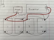
I’m just getting my head around the battery wiring/charge controller wiring for the multiple batteries and where to put the inverter points.

I’ve come up with a basic diagram, I’ve omitted the extra 4 batteries fuses/switches for the sake of simplicity.(Both the inverter and mppt will be fused and on there own isolation switch to/from the batteries).

8C94118C-0808-4B1F-8025-9DE4EDF3C907.jpeg
Now I think I’ve got the jist of it but I’m not sure if the inverter pos should be on no1 pos terminal or no3. I don’t want to drain one set of batteries or charge one lot more than the other all things trying to be equal.

If you have any pointers on this it would be appreciated.

I’ve had a read through the victron wiring book and think I’ve come up with the appropriate diagram just not 100%.

Cheers all.
 
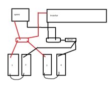
On your #4 terminal would be the place to install the shunt so all your Neg- wires connect to the P- side of the shunt and the B- connects to the batteries.

Bus bars are the easiest solution to the balancing problem, it brings everything to a central point. Krappy MSPaint drawing to follow:

24v wiring.jpg
 
Appreciate the info as always, every days a school day and all that. I think for the time being Il stick with the 24v system. Get it all up and running and if expansion is needed then go 48v. M

I’m just getting my head around the battery wiring/charge controller wiring for the multiple batteries and where to put the inverter points.

I’ve come up with a basic diagram, I’ve omitted the extra 4 batteries fuses/switches for the sake of simplicity.(Both the inverter and mppt will be fused and on there own isolation switch to/from the batteries).

Now I think I’ve got the jist of it but I’m not sure if the inverter pos should be on no1 pos terminal or no3. I don’t want to drain one set of batteries or charge one lot more than the other all things trying to be equal.

If you have any pointers on this it would be appreciated.

I’ve had a read through the victron wiring book and think I’ve come up with the appropriate diagram just not 100%.

Cheers all.
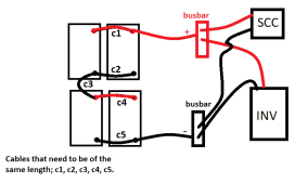
Regardless of the number of batteries, best to look at it all as a single battery bank.

With that said, there should be only two main battery terminals, one positive and one negative. (in the diagram you've shared, that is not the case. SCC is connected to one of the battery's positive terminals while the Inverter is on another)

Best to use Busbars as a point of connecting devices to the battery main cables.

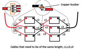
In addition, it's important that all the cables for all 4 of the battery interconnections are of the same length.

The main Positive and Negative cables can be of different lengths.

I've made this diagram for your consideration.

The battery storage consists of 4 batteries/ two pairs of 2x12V batteries in parallel and then the pairs are connected into series to make a 24V storage.
 

Attachments

  • Wiring_Suggestion.png
    Wiring_Suggestion.png
    21.4 KB · Views: 9
On your #4 terminal would be the place to install the shunt so all your Neg- wires connect to the P- side of the shunt and the B- connects to the batteries.

Bus bars are the easiest solution to the balancing problem, it brings everything to a central point. Krappy MSPaint drawing to follow:

View attachment 136853
Appreciate your input, thought I’d got it off kilter but glad I asked.
Busbars are on the order list for sure looking at the amount of points to connect up it makes sense.

Cheers again.
 
Regardless of the number of batteries, best to look at it all as a single battery bank.

With that said, there should be only two main battery terminals, one positive and one negative. (in the diagram you've shared, that is not the case. SCC is connected to one of the battery's positive terminals while the Inverter is on another)

Best to use Busbars as a point of connecting devices to the battery main cables.

In addition, it's important that all the cables for all 4 of the battery interconnections are of the same length.

The main Positive and Negative cables can be of different lengths.

I've made this diagram for your consideration.

The battery storage consists of 4 batteries/ two pairs of 2x12V batteries in parallel and then the pairs are connected into series to make a 24V storage.
Makes sense thinking of it as one big one rather than multiple individual batteries.

Ah didn’t realise that all the main link ones are for series but both parallel are longer will get them cut down and crimped.

That diagram took a bit of working out on the battery config side, not seen a diagram with one link in the middle there all on the outer pos/negs bar the series connection) but I’ve got it.

Currently charging all the batteries individually and taking electrolyte readings keeping a database for keeping tabs on them.

Il have the busbars delivered tomorrow, and will start wiring them in if all the batteries are good to go.

Appreciate the info and help as always.

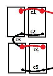
Sorry for the hard-to-read diagram. MSpaint can only get you so far :)

Here's one with the positive battery terminals enlarged for easier reading.

As you can see, each parallel string in this battery bank has a diagonally opposite terminal used for the main connections. This is so, the charge/load is shared equally across the two batteries.
Wiring_24V200Ah.png

Both of the suggested diagrams, Rednecktek's or mine will work just fine.

Best,
D.
 
Last edited:
Sorry for the hard-to-read diagram. MSpaint can only get you so far :)

Here's one with the positive battery terminals enlarged for easier reading.

As you can see, each parallel string in this battery bank has a diagonally opposite terminal used for the main connections. This is so, the charge/load is shared equally across the two batteries.
View attachment 136875

Both of the suggested diagrams, Rednecktek's or mine will work just fine.

Best,
D.
Your diagram was fine to understand I was trying to understand how the flow of current would work through the batteries for the series/parallel configuration. But I got it in the end haha.

Well I finally got round to redoing the wiring and still awaiting on the busbars to be delivered (delivery error so delayed).

Everything is now charging and all linked up with the smartshunt. So I had the 200w of panels out today to test the whole setup - fridge and freezer plumbed in and all looks pretty great not going to lie. Only using 4 fully charged batteries right now wired in with your above diagram, whilst I charge the other 4 individually to 100%.

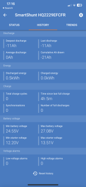
The only oddity I’ve now got is the smart shunt. It’s logging everything, bar the charge energy. And I cannot fathom why.
Shunt is in the neg side with the v bat and the aux on the two pos terminals (v-bat is too main load pos which the mppt is also wired up too.

1785346F-9D32-40F4-9B9E-168FE31023C6.png

Once I’d fully charged and wired I calibrated the shunt battery capacity to 230ah and set the 100% soc. So unsure what the issue is if you have any suggestions I’d be grateful.
 
Last edited:
Well I finally got round to redoing the wiring and still awaiting on the busbars to be delivered (delivery error so delayed).

Everything is now charging and all linked up with the smartshunt. So I had the 200w of panels out today to test the whole setup - fridge and freezer plumbed in and all looks pretty great not going to lie. Only using 4 fully charged batteries right now wired in with your above diagram, whilst I charge the other 4 individually to 100%.

Nice! (y)

The only oddity I’ve now got is the smart shunt. It’s logging everything, bar the charge energy. And I cannot fathom why.
Shunt is in the neg side with the v bat and the aux on the two pos terminals (v-bat is too main load pos which the mppt is also wired up too.

View attachment 137890

Once I’d fully charged and wired I calibrated the shunt battery capacity to 230ah and set the 100% soc. So unsure what the issue is if you have any suggestions I’d be grateful.

Curious about why is the capacity set at 230Ah? I thought you were using 12V 100Ah batteries.


Best,
D.
 
Last edited:
Only using 4 fully charged batteries right now wired in with your above diagram, whilst I charge the other 4 individually to 100%.

Just realized I forgot to mention that since you are using the suggested diagram for wiring, you could use a single battery balancer in between the two parallel strings to keep your series string balanced. https://www.victronenergy.com/batteries/battery-balancer

From what I've read, these balancers are just about perfect for lead-acid batteries. More so than for LiFePo4. Haven't personally used one yet, but looks pretty straightforward.

Best,
D.
Appreciate the advice on the balancers, Il have to pick one up.

So far the batteries have kept fairly well balanced in the above config, still need to put the busbars in and sort the wiring, just not had a minute spare ?.

Out of curiosity how would you wire in another two batteries to the above setup?

I’m eventually going to have 2 banks of 6 batteries and with the busbars it would be a doddle. Current setup is two of the above both separate.

But I cannot fathom how 6 would stay balanced within that config without a balancer.
Ideally, adding another 4 batteries to the mix would probably be easier to wire.

As far as adding just two more, six in total, I'd probably go with something like this;

Wiring__.png

You can buy flat copper rods at your local hardware store for cheap and make your own busbar pieces. I'd suggest a minimum thickness of 5mm x 40mm width flat copper rod. Rule of thumb, that's worth about 240A-ish busbar. @24V system voltage that should be plenty, good for 5000W+ AC on the inverter side.

Hope it helps a bit.

Edit:
If you make your own, would be wise to make the busbar pieces a bit longer to have enough room for mounting holes. If possible, screw the busbar to an FR4/G10 piece and then fix the FR4/G10 piece with standoffs to the wiring board surface. This will isolate the busbar from the mounting hardware/board, electrically and thermally. A polycarbonate busbar 'holder' mount would do too.
 
Last edited:
I’m eventually going to have 2 banks of 6 batteries and with the busbars it would be a doddle. Current setup is two of the above both separate.

But I cannot fathom how 6 would stay balanced within that config without a balancer.
See the above diagram.

Just combine the main cables of the two 24V battery banks with a busbar and then to the system. The two battery banks will then be in parallel, sharing current and balancing each other.

1 balancer per bank of 6 batteries, which only needs to balance the two 12V sides of a 24V bank. Within the 12V side, the three parallel batteries will do the balancing between each other.

The balancer is connected to the main + busbar and the main - busbar, and in this case another wire to the middle busbar, the one where two 12V are connected in series.

 
Last edited:
Back
Top