diy solar

diy solar

Solar Configuration Review/Questions

myrkr

New Member
Joined
Mar 9, 2020
Messages
63
Originally posted this in Vehicle Mounted Systems but didn't get any feedback, so thought maybe I should post in the general DIY instead

Working on installing the solar portion of my electrical system in my van and wanted to get some feedback. I've been reading/referencing the https://diysolarforum.com/resources/fusing-wire-sizing-guidelines-for-solar-panels.143/ to help figure this out.

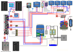
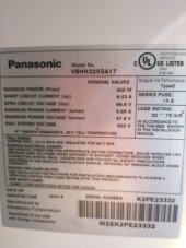
I've attached the panel specs as well as my wiring schematic. At this point I'm just focused on getting the solar installed so you can ignore everything else on the schematic.

Panel Specs
Max Power (Pmax) 325W
Short Circuit Current (Isc) 6.03A
Open Circuit Voltage (Voc) 69.6V
Maximum Power Current (Ipmax) 5.65A
Maximum Power Voltage (Vpmax) 57.6V
Max system Voltage 600V
Series Fuses 15A

My planned configuration

3X Panels in Parallel
MC4 3to1 Merge Connectors to Connect Panels
MC4 Panel Fuse 15A on each Positive Connection from Panel to Merge Connection
10 Feet of 10AWG wire from branch connector to inside van connecting to dual pole disconnect switch
10 Feet of 10AWG from dual pole disconnect switch to Victron 100|50 MPPT
2 Feet of 10AWG from Victron 100|50 MPPT to 60AMP Blue Sea Breaker
60 AMP Blue Sea Breaker Connects to Blue Sea Disconnect Switch

My battery bank is 24V so everything after MPPT is 24V (or 28V I guess) which I assume should mean my breaker and disconnect switch are fine since they are rated for up to 48V.

So for my configuration I believe my calculation for wire sizing and fusing is based off the following

3P (panel specs above)
Voltage - 58V
Current - 18A

Wire sizing I'm using the above voltage and current numbers and multiplying by 1.56, so I get the following

Voltage - 58V x 1.56 = 90V
Current - 18A x 1.56 = 28A

So for wire from MC4 merge connectors to the MPPT I come up with 20 feet one way, or 40 feet total, at 90V with 28A, so 10AWG at 1.5% voltage drop. For derating the wires will be on the roof of the van, but under the panels, in an 1"x1" or possibly larger square conduit.

Questions
1. I'm unclear on the single MC4 fuse sizing and must be missing this somewhere in the explanation. I have it at 15A right now which is the same as the panel series fuse rating, but should it be 10A instead?
2. Is my math/understanding of the 156% multiplier correct for both voltage and current?
3. Should I consider 8AWG in place of the 10AWG as that would get me to 1% voltage drop?
4. Originally I was going to use a dual pole circuit breaker as shown in the schematic to serve as a disconnect/protection for the MPPT. But after reading it seems like the current recommendation is to use a dual pole switch instead. I like the idea of using the circuit breaker for the added protection, but is that not advised and I should only use a switch?

Thanks for the help
 

Attachments

  • Transit Electrical System V2.5TF4x3.png
    Transit Electrical System V2.5TF4x3.png
    883.9 KB · Views: 9
  • IMG_20230605_193451815.jpg
    IMG_20230605_193451815.jpg
    99.4 KB · Views: 8
Sorry you're having difficulty getting any non spam replies. This isn't the norm for this forum. I;m sure somebody will chime in with a reasonable reply.
The panels you are using are unusually high voltage for their low wattage. Hopefully you haven't bought them yet. If you look around you will find 60 cell panels with much lower Voc. This will allow you to series wire your panels in a single string, requiring no fusing. You may want a higher Voc MPPT CC to do this still but you will still be ahead of the game with much simplified wiring and parts count.
 
Questions
1. I'm unclear on the single MC4 fuse sizing and must be missing this somewhere in the explanation. I have it at 15A right now which is the same as the panel series fuse rating, but should it be 10A instead?
2. Is my math/understanding of the 156% multiplier correct for both voltage and current?
3. Should I consider 8AWG in place of the 10AWG as that would get me to 1% voltage drop?
4. Originally I was going to use a dual pole circuit breaker as shown in the schematic to serve as a disconnect/protection for the MPPT. But after reading it seems like the current recommendation is to use a dual pole switch instead. I like the idea of using the circuit breaker for the added protection, but is that not advised and I should only use a switch?
1. 10 or 15 are both ok.
2. 156% is for current only. You can adjust PV panel voltage for low temps by multiplying by 125%, which will get an Voc good to -40c/f
3. The length of the run should be short enough you don't need to worry about voltage drop.
4. a switch is all that is needed, but a breaker will also be acceptable here.
 
Sorry you're having difficulty getting any non spam replies. This isn't the norm for this forum. I;m sure somebody will chime in with a reasonable reply.
The panels you are using are unusually high voltage for their low wattage. Hopefully you haven't bought them yet. If you look around you will find 60 cell panels with much lower Voc. This will allow you to series wire your panels in a single string, requiring no fusing. You may want a higher Voc MPPT CC to do this still but you will still be ahead of the game with much simplified wiring and parts count.
Thank you! I happen to already have the panels as they were the perfect size for my van. I'm pretty close to starting to assemble my junction box, just sourcing the last components.

1. 10 or 15 are both ok.
2. 156% is for current only. You can adjust PV panel voltage for low temps by multiplying by 125%, which will get an Voc good to -40c/f
3. The length of the run should be short enough you don't need to worry about voltage drop.
4. a switch is all that is needed, but a breaker will also be acceptable here.
Thank you! Much appreciated!

I've got things fairly close now and have most of the components for my junction box which I'm using to tie everything together. I've got a fuse block for the positive sides and then busbars for negative and positive out to my switch. The only component I have left to source is the smaller copper lugs for the 12AWG cable. It seems like 8AWG is the smallest size for Ancor, Bay Marine, Selterm, etc. I'm only finding generic Amazon ones in the 12AWG size, so I need to search more to try and find higher quality 12AWG copper lugs. Open to suggestions!
 
Thank you! I happen to already have the panels as they were the perfect size for my van. I'm pretty close to starting to assemble my junction box, just sourcing the last components.


Thank you! Much appreciated!

I've got things fairly close now and have most of the components for my junction box which I'm using to tie everything together. I've got a fuse block for the positive sides and then busbars for negative and positive out to my switch. The only component I have left to source is the smaller copper lugs for the 12AWG cable. It seems like 8AWG is the smallest size for Ancor, Bay Marine, Selterm, etc. I'm only finding generic Amazon ones in the 12AWG size, so I need to search more to try and find higher quality 12AWG copper lugs. Open to suggestions!
Electronics supplier DigiKey has a selection of terminals for 12AWG, from good brands like 3M or TE, see and find one that matches the bolt/screw size you need: https://www.digikey.com/short/hwr99hd3
 
4. Originally I was going to use a dual pole circuit breaker as shown in the schematic to serve as a disconnect/protection for the MPPT. But after reading it seems like the current recommendation is to use a dual pole switch instead. I like the idea of using the circuit breaker for the added protection, but is that not advised and I should only use a switch?
Breakers can be rated to shut off at max amperage hundreds of times, but most switches you see used here are not rated for shutoff under load.

I’m not sure what type of dual pole switch you mean. Whatever it is, make sure it’s DC rated.

I have up to 20 amps at 65 volts and I use single pole dc breakers for my solar panels from mid note solar.
3. Should I consider 8AWG in place of the 10AWG as that would get me to 1% voltage drop?
I’m not sure where you mean.

If this is panels, a few percentage is minutes of charging, no real difference.

MC4s just take 10 AWG and smaller. Also, make sure your device it connects to can take the wire. On a smaller Victron, I wanted to use 8AWG for voltage loss, but the controller just took 10.

——-//
A couple of system comments,

-I’m not sure I’d fuse each battery to 300 amps. My 24 volt 3000 watt inverter has a 125 amp fuses on each battery, and 225 amp fuse after combined. I use 4/0 wire.

-I don’t have the same equip as you, but for my arcing from startup for my converter, inverter, and battery charger, I use a pre charge resistor on a battery switch. I recommend something.

-I’m confused what you have so many dc converters for.
-If this is a mobile build, I’m not sure 20 amps is enough for that converter.
 
3. Should I consider 8AWG in place of the 10AWG as that would get me to 1% voltage drop?
In your case you need only be concerned with voltage drop between the SCC and the battery bank. The accurate voltage reading is important for charging. If your controller thinks the voltage is higher than the actual battery voltage you end up with undercharged batteries.
 
Breakers can be rated to shut off at max amperage hundreds of times, but most switches you see used here are not rated for shutoff under load.

I’m not sure what type of dual pole switch you mean. Whatever it is, make sure it’s DC rated.

I have up to 20 amps at 65 volts and I use single pole dc breakers for my solar panels from mid note solar.

I’m not sure where you mean.

If this is panels, a few percentage is minutes of charging, no real difference.

MC4s just take 10 AWG and smaller. Also, make sure your device it connects to can take the wire. On a smaller Victron, I wanted to use 8AWG for voltage loss, but the controller just took 10.

——-//
A couple of system comments,

-I’m not sure I’d fuse each battery to 300 amps. My 24 volt 3000 watt inverter has a 125 amp fuses on each battery, and 225 amp fuse after combined. I use 4/0 wire.

-I don’t have the same equip as you, but for my arcing from startup for my converter, inverter, and battery charger, I use a pre charge resistor on a battery switch. I recommend something.

-I’m confused what you have so many dc converters for.
-If this is a mobile build, I’m not sure 20 amps is enough for that converter.

Thank you for the feedback!

The switch I had purchased to use was this one https://shop.explorist.life/shop/all-products/solar-isolator-disconnect/ which seemed to fit the need, but I wonder now about shutting off under load and if that might cause damage to the switch or elsewhere? I assumed since it was being used in kits sold by that company that it was fit for that purpose. My original plan as you saw in the schematic was to have a breaker instead. I could go back to the breaker option if need be.

For the battery fuses those are the factory installed fuses that came with the batteries from BigBattery. I think I could replace the fuses with a lower amperage fuse though. Was the 125 amp fuses you used based on a calculation and then safety factor?

For the precharge resistor I think this was something I had read about before, but I might be thinking of the wrong thing. Is this to limit the initial flow once I turn the system on to avoid popping breakers and blowing fuses elsewhere? If so do I place the precharge resistor right after my battery switch? Oh, and is this something I can just buy as a premade offering or do I have to buy components and build one?

The x4 DC converters was to be able to pull more amps from my vehicle alternator system and charge the house batteries faster. Victron didn't offer at the time a single solution that could do more amps in one unit. So they suggested running multiple units, so this would get me 120 amps (12V) converted over to 60 amps (24V) for charging. I have dual alternators and my maximum continuous draw the vehicle system will allow is 120 amps, but I plan to set the Victrons to operate under this maximum with some cushion since I probably won't need that much charging and I know the DC converters will get hot and start to lose efficiency.
 
The switch I had purchased to use was this one https://shop.explorist.life/shop/all-products/solar-isolator-disconnect/ which seemed to fit the need, but I wonder now about shutting off under load and if that might cause damage to the switch or elsewhere?
I am by no means an expert on switches, but that switch may work. I have not seen a plastic disnnect switch before.
For the battery fuses those are the factory installed fuses that came with the batteries from BigBattery. I think I could replace the fuses with a lower amperage fuse though. Was the 125 amp fuses you used based on a calculation and then safety factor?

If you have a 300 amp fuse, the wiring would need to handle 300 amps.

The 125 amp fuse was based off a calculation. Short version is something that could handle a 2000 watt per battery load at the inverter low cuttoff voltage of 20 volts. This does provide enough power to run single high wattage appliances like a air conditioner, but will not allow me to max the inverter out. If the two batteries are in parallel, that provides enough power for the inverter.

For the precharge resistor I think this was something I had read about before, but I might be thinking of the wrong thing. Is this to limit the initial flow once I turn the system on to avoid popping breakers and blowing fuses elsewhere? If so do I place the precharge resistor right after my battery switch? Oh, and is this something I can just buy as a premade offering or do I have to buy components and build one?
There's plenty of info on the forum, I bought a blue sea switch and resistor and built mine with this forum resource:


Others have used a lightbulb, inline resistor, or momentary switch connected to a resistor.
 
The x4 DC converters was to be able to pull more amps from my vehicle alternator system and charge the house batteries faster. Victron didn't offer at the time a single solution that could do more amps in one unit. So they suggested running multiple units, so this would get me 120 amps (12V) converted over to 60 amps (24V) for charging. I have dual alternators and my maximum continuous draw the vehicle system will allow is 120 amps, but I plan to set the Victrons to operate under this maximum with some cushion since I probably won't need that much charging and I know the DC converters will get hot and start to lose efficiency.
That will work. I have three SCCs for my system and the Victron does not allow me to set an overall max limit, but can set each device individually.

Before you buy all those, you could get data to see how much you actually need. I spent a lot of time on calculations, and it got me close, but actually using my setup, I ended up adding more solar panels, but did not need any vehicle charging. I do have a generator and AC to DC converter to use if needed, but I have not needed.

I think two alternators is a good idea for so much charging,
 
Back
Top