Working on installing the solar portion of my electrical system and wanted to get some feedback. I've been reading/referencing the https://diysolarforum.com/resources/fusing-wire-sizing-guidelines-for-solar-panels.143/ to help figure this out.
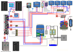
I've attached the panel specs as well as my wiring schematic. At this point I'm just focused on getting the solar installed so you can ignore everything else on the schematic.
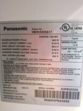
Panel Specs
Max Power (Pmax) 325W
Short Circuit Current (Isc) 6.03A
Open Circuit Voltage (Voc) 69.6V
Maximum Power Current (Ipmax) 5.65A
Maximum Power Voltage (Vpmax) 57.6V
Max system Voltage 600V
Series Fuses 15A
My planned configuration
3X Panels in Parallel
MC4 3to1 Merge Connectors to Connect Panels
MC4 Panel Fuse 15A on each Positive Connection from Panel to Merge Connection
10 Feet of 10AWG wire from branch connector to inside van connecting to dual pole disconnect switch
10 Feet of 10AWG from dual pole disconnect switch to Victron 100|50 MPPT
2 Feet of 10AWG from Victron 100|50 MPPT to 60AMP Blue Sea Breaker
60 AMP Blue Sea Breaker Connects to Blue Sea Disconnect Switch
My battery bank is 24V so everything after MPPT is 24V (or 28V I guess) which I assume should mean my breaker and disconnect switch are fine since they are rated for up to 48V.
So for my configuration I believe my calculation for wire sizing and fusing is based off the following
3P (panel specs above)
Voltage - 58V
Current - 18A
Wire sizing I'm using the above voltage and current numbers and multiplying by 1.56, so I get the following
Voltage - 58V x 1.56 = 90V
Current - 18A x 1.56 = 28A
So for wire from MC4 merge connectors to the MPPT I come up with 20 feet one way, or 40 feet total, at 90V with 28A, so 10AWG at 1.5% voltage drop. For derating the wires will be on the roof of the van, but under the panels, in an 1"x1" or possibly larger square conduit.
Questions
1. I'm unclear on the single MC4 fuse sizing and must be missing this somewhere in the explanation. I have it at 15A right now which is the same as the panel series fuse rating, but should it be 10A instead?
2. Is my math/understanding of the 156% multiplier correct for both voltage and current?
3. Should I consider 8AWG in place of the 10AWG as that would get me to 1% voltage drop?
4. Originally I was going to use a dual pole circuit breaker as shown in the schematic to serve as a disconnect/protection for the MPPT. But after reading it seems like the current recommendation is to use a dual pole switch instead. I like the idea of using the circuit breaker for the added protection, but is that not advised and I should only use a switch?
Thanks for the help
I've attached the panel specs as well as my wiring schematic. At this point I'm just focused on getting the solar installed so you can ignore everything else on the schematic.
Panel Specs
Max Power (Pmax) 325W
Short Circuit Current (Isc) 6.03A
Open Circuit Voltage (Voc) 69.6V
Maximum Power Current (Ipmax) 5.65A
Maximum Power Voltage (Vpmax) 57.6V
Max system Voltage 600V
Series Fuses 15A
My planned configuration
3X Panels in Parallel
MC4 3to1 Merge Connectors to Connect Panels
MC4 Panel Fuse 15A on each Positive Connection from Panel to Merge Connection
10 Feet of 10AWG wire from branch connector to inside van connecting to dual pole disconnect switch
10 Feet of 10AWG from dual pole disconnect switch to Victron 100|50 MPPT
2 Feet of 10AWG from Victron 100|50 MPPT to 60AMP Blue Sea Breaker
60 AMP Blue Sea Breaker Connects to Blue Sea Disconnect Switch
My battery bank is 24V so everything after MPPT is 24V (or 28V I guess) which I assume should mean my breaker and disconnect switch are fine since they are rated for up to 48V.
So for my configuration I believe my calculation for wire sizing and fusing is based off the following
3P (panel specs above)
Voltage - 58V
Current - 18A
Wire sizing I'm using the above voltage and current numbers and multiplying by 1.56, so I get the following
Voltage - 58V x 1.56 = 90V
Current - 18A x 1.56 = 28A
So for wire from MC4 merge connectors to the MPPT I come up with 20 feet one way, or 40 feet total, at 90V with 28A, so 10AWG at 1.5% voltage drop. For derating the wires will be on the roof of the van, but under the panels, in an 1"x1" or possibly larger square conduit.
Questions
1. I'm unclear on the single MC4 fuse sizing and must be missing this somewhere in the explanation. I have it at 15A right now which is the same as the panel series fuse rating, but should it be 10A instead?
2. Is my math/understanding of the 156% multiplier correct for both voltage and current?
3. Should I consider 8AWG in place of the 10AWG as that would get me to 1% voltage drop?
4. Originally I was going to use a dual pole circuit breaker as shown in the schematic to serve as a disconnect/protection for the MPPT. But after reading it seems like the current recommendation is to use a dual pole switch instead. I like the idea of using the circuit breaker for the added protection, but is that not advised and I should only use a switch?
Thanks for the help