diy solar

diy solar

Solar Expert needed for correct sizing of inverter/optimizers/batteries that match qty of 30 REC 360w panels

OK I think I am heading down the right path after a month of investigating, discussing and finally going with the EG4-18kPV and because of the NEM3 net metering requirements, three of the EG4 PowerPro 14.3 kWh wall mount batteries, all compliant with California BS requirements.
I'm headed basically the same way for a Florida system. I haven't quite chosen between the EG4 PowerPro or a set of rack batteries. Each has its own benefits. The 18KPV does integrate a lot of stuff and I am definitely a minimalist when it comes to having boxes.


-The noise level at full load vs others was much less through my investigations.
Interesting. I thought the 18KPV was considered loud by some folks.

-The ease of installation with the matching batteries was a big plus. Batteries include conduit boxes and all paralleling cables.
One thing I do not like about the EG4 setup is the stacking of the inverter on the battery means you have to unstack the inverter and wire chase to replace the battery. I grant it all looks nice, but there's a hidden cost to that in the future. Taking down the inverter just to free the battery is a major effort depending on how fixed all the conduits end up being into the junction box.

-No optimizers as the extra cost at this time does not make sense. No chance of shading outside of clouds.
I agree. If shading is not an issue, optimizers are useless. That is the same with my system.

Worked with GreenLancer on the drawings for submitting to SLO County Building department and PG&E. This was a relatively painless process as I also needed to receive the Electrical Engineering stamps through them.
I am starting to sense they might be the go to folks for my drawings, too.

I’ve attached the drawing below for feedback from all in the case I am missing something that needs attention early on.
I have questions about your drawing, forgive me if they are stupid.

A. Main Panel Back Feed

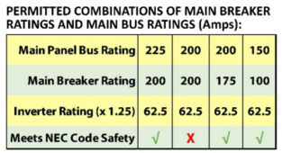
In your main panel, you are using a 100 A back feed breaker with a 200 A service. I thought there was a code requirement (as indicated in the 18KPV manual) that the panel bus bars had to be larger the main breaker by some rule. Here is the chart in the manual:
1709498883787.png

One of the questions I face is if my main panel has 225 A bus bars with a 200 A breaker so I can back feed with a 70 A breaker. Your drawing clearly goes off chart. The reason this limit exists is that if you draw 200 A from the grid and pull power from your inverter at the same time, you will go over the bus bar rating. You can a little over it because you can place your back feed breaker at the opposite end of the bus bar and thus split the loads up. As drawn, your 100 A back feed breaker is at the top of your breaker stack and it needs to be at the bottom for this bus bar reason.

B. AC Disconnect

Like usual, there is an AC disconnect from the inverter to the main panel. But that disconnect actually does almost nothing. If you pull it, the main panel is hot from the grid, the subpanel is hot from the inverter, the batteries are hot supply the inverter, and the solar lines are hot if there is sunlight. So why does this disconnect exist? It is a useless box, IMO, and I haven't found anyone who can explain its purpose other than uselessly saying it is required by code. The code usually has logical reasons, but that escapes me here.

C. Rapid Shutdown

I get it that your ground array doesn't need per panel rapid shutdown thus avoiding a per panel RSD device. But that doesn't seem to negate all need for RSD at the inverter and battery level. Given the AC disconnect doesn't do hardly anything, you probably still need an RSD button where a firefighter can activate it. This would shutdown the batteries and the inverter. If the utility meter is pulled that shuts down the grid and everything except the PV lines are now cold. The PV can be shutdown with the DC disconnect. Without RSD, you can't shut down the inverter or batteries so the subpanel is still hot. Maybe this is detailed on another drawing?

D. Bypass Ability

In this system design, all sub panel power must pass through the inverter. If the inverter never fails, no problem. But if you have an issue with it and want to service it, you are forced to shutdown everything on the sub panel, which should be the most critical loads in your house. If you put in a manual transfer switch, it can allow the sub panel to be powered from the inverter as drawn, or it could allow selecting a breaker in the main panel to bypass the inverter. In that case, you can turn off the main panel back feed breaker and flip the transfer switch and now the inverter is AC isolated from your house where everything, main and sub panel, are now on the grid. People who don't plan for failures or service usually regret it.

My main annoyance with the transfer switch is that USA legal options are ugly, big, and expensive. The European ones are so much nicer, but, alas, not legal here.

E. Minor Nits

The 18 KPV is shown with 3 battery terminals, it has only 2.

EMT is called out for most of your conduit. My understanding is that EMT is required for the PV wiring indoors but otherwise I thought PVC conduit was usable elsewhere. PVC conduit is cheaper, easier to install and lasts longer.

Mike C.
 
I’ve attached the drawing below for feedback from all in the case I am missing something that needs attention early on.
Glad to see the progress in your project, you're proceeding much more efficiently than I did on mine. BTW you have your personal info on these plans.

Maybe it is in another diagram, but you should have a CT sensor going from EG4 to your main panel. Without that, you can only do self consumption on the loads in the subpanels. On NEM3 this would be bad since you're paying more money to PG&E (or whoever your usurious POCO is).

As the other user said, your backfeed is too big for the MSP, and you need the 100A breaker on the bottom. You need to go down to 175A on the main with 62.5A (125% * output rating) of a single 18kpv. If you might add a second 18kpv in the future then the breaker will have to be further reduced. OR you use a different backfeed rule.

I don't know if EG4 supports zero export config in a way that California / AHJ / POCO accepts. In that case you might be able to count it as 0A of inverter output.

NOW, it is possible that you qualify under 100% rule, in that case your load breakers need to be itemized, and you count the backfeed as 100A IIRC, not 62.5A (I don't have the book opened to that section).

Make sure you get clear impact protection / maximum amount of batteries in one location calculations from Greenlancer. I don't remember what the maximum outdoor amount allowed under California code is. I believe the installation instructions require the batteries to be right next to each other (and the massive cables you need for 48V also strongly encourages that)

Interesting. I thought the 18KPV was considered loud by some folks.
There are MUCH louder pieces of equipment commonly used on this forum.

In your main panel, you are using a 100 A back feed breaker with a 200 A service. I thought there was a code requirement (as indicated in the 18KPV manual) that the panel bus bars had to be larger the main breaker by some rule. Here is the chart in the manual:


One of the questions I face is if my main panel has 225 A bus bars with a 200 A breaker so I can back feed with a 70 A breaker. Your drawing clearly goes off chart. The reason this limit exists is that if you draw 200 A from the grid and pull power from your inverter at the same time, you will go over the bus bar rating. You can a little over it because you can place your back feed breaker at the opposite end of the bus bar and thus split the loads up. As drawn, your 100 A back feed breaker is at the top of your breaker stack and it needs to be at the bottom for this bus bar reason.

The manual only has the simplified rule (120%).

Yes you should always have the backfeed breaker at the bottom since that is required for 120% rule.

Note that the 120% rule calculation is actually based on 125% * inverter output current, not the breaker size.

Like usual, there is an AC disconnect from the inverter to the main panel. But that disconnect actually does almost nothing. If you pull it, the main panel is hot from the grid, the subpanel is hot from the inverter, the batteries are hot supply the inverter, and the solar lines are hot if there is sunlight. So why does this disconnect exist? It is a useless box, IMO, and I haven't found anyone who can explain its purpose other than uselessly saying it is required by code. The code usually has logical reasons, but that escapes me here.

You need a servicing disconnect. In my location a breaker is fine.

(Yes, it's also required by code sometimes).

I get it that your ground array doesn't need per panel rapid shutdown thus avoiding a per panel RSD device. But that doesn't seem to negate all need for RSD at the inverter and battery level. Given the AC disconnect doesn't do hardly anything, you probably still need an RSD button where a firefighter can activate it. This would shutdown the batteries and the inverter. If the utility meter is pulled that shuts down the grid and everything except the PV lines are now cold. The PV can be shutdown with the DC disconnect. Without RSD, you can't shut down the inverter or batteries so the subpanel is still hot. Maybe this is detailed on another drawing?
You do need a battery shutdown switch. If the inverter is outside then they can press the button on the inverter. This shutdown switch will need to be on the system map placard
 
You need a servicing disconnect. In my location a breaker is fine.
The AC disconnect doesn't do anything for servicing over flipping the breaker.

The 18KPV manual states it has to be outside the building and near the service entrance for access by first responders which indicates it is a safety requirement. But yet, it doesn't make anything safe at all.

(Yes, it's also required by code sometimes).
Why? It doesn't do anything, all the voltages are hot after you pull it. Main is still hot from grid, sub panel is hot from inverter, PV lines are hot, and battery lines are hot. What did we make safe?

It seems dangerous to imply something became safe when you pull the AC disconnect when in fact nothing became safe. When I see stuff like that, I sense there has been some misinterpretation of the code, or at least, the code isn't based on reality.

Mike C.
 
Taking down the inverter just to free the battery is a major effort depending on how fixed all the conduits end up being into the junction box.
Is this something you were planning on doing frequently? Battery life ought to be on the order of 20 years, and at that point, there are probably better inverters and better batteries to install in place of all of that anyway.
 
Battery life ought to be on the order of 20 years, and at that point, there are probably better inverters and better batteries to install in place of all of that anyway.
I try to think longer term than that. I find it particularly annoying when system design makes servicing very difficult.

PowerPro warranty is 10 years, so they aren't all that confident on the 20 year thing.

Do you want to take down the whole inverter to fix/replace a battery? Batteries impress me as the system component that will need servicing more than any other.

This is one aspect that favors the rack batteries.

Mike C.
 
But yet, it doesn't make anything safe at all.
It’s likely a holdover from interactive grid tie inverters where it actually makes sense.

There are also rules around whether solar disconnect must be independent from load breakers. Probably this is to allow the house to still have lights with solar off, which is a slight safety improvement. Maybe.
It seems dangerous to imply something became safe when you pull the AC disconnect when in fact nothing became safe.

The important thing to verify is RSD activated and battery cuts off. The AC disconnect is not going to do this on a hybrid.

It may be necessary to turn off both AC and battery/solar shutoff on some inverters, so maybe the fire responders like to flip both. There are probably some edge cases like inverter is melted but disconnect is OK, where having some redundancy is good. A melted inverter could conceivably fail short within the bypass relay. I’m stretching here 🤷

Regardless you have to bend over backwards / path of least resistance with the AHJ/POCO. If the fire marshal wants you to spend $500 on a lockable knife disconnect, the other choice is to forgo solar 🤷 . Or participate in democracy
 
Last edited:
Do you want to take down the whole inverter to fix/replace a battery? Batteries impress me as the system component that will need servicing more than any other.
There’s arguably more things that can break in a hybrid.

Battery just has 16 cells (passive-ish chemical elements), BMS which has sensors, wires, cutoff FETs, busbars, comms board.

48V Battery is probably more user serviceable because worst case you can just swap out BMS and go to open loop. If there are special purpose critical path boards that break on the hybrid. Have fun fixing it…
 
There’s arguably more things that can break in a hybrid.
If an inverter breaks, it usually either can't power anything or has a fault that blows breakers. If it has some weird fault that allows it to generate power without tripping, then it could power a down grid in an outage. The UL and code standards have accepted that risk through testing and design standards.

The point is to make the building safe. Pulling that AC disconnect doesn't do squat to accomplish that.

Pushing RSD does do it, and that's part of the standards to make that work. It interrupts a critical voltage that if absent, prevents the inverter from driving the grid, driving the load panels, and further disables the batteries.

Buying a deceptive and useless $500 box for some inspector to sign off is lame, but I guess we have to do that if required. I really hate useless things, particularly ones that are deceptive. If the first responder was presented only with the big red RSD button, that will get pressed. If they have the AC disconnect, they might pull it and not press the button. You know that will happen someday.

Mike C.
 
If an inverter breaks, it usually either can't power anything or has a fault that blows breakers. If it has some weird fault that allows it to generate power without tripping, then it could power a down grid in an outage. The UL and code standards have accepted that risk through testing and design standards.
This was in regards to the failure analysis you had posted regarding the serviceability of batteries vs inverters.

Buying a deceptive and useless $500 box for some inspector to sign off is lame, but I guess we have to do that if required.

The first cut of plans drafted for my system took the most conservative approach - knife disconnect, no load circuits disconnected. That would have added 50+ ft + 100A knife disconnect to my system. I guess they wanted to minimize the chance of a rejection. Since I have done a previous system with this AHJ/POCO I knew it was not needed by either authority.

The documentation is not clear at all, you just need to know. (And the one piece of documentation that has it, on the POCO side interconnection application, has a scary SLD that implies you need a cleanly separated disconnect, but if you read some terribly written English on that page you can sort of see that there are generous exemptions).

I really hate useless things, particularly ones that are deceptive. If the first responder was presented only with the big red RSD button, that will get pressed. If they have the AC disconnect, they might pull it and not press the button. You know that will happen someday.
I believe you're allowed to have multiple grouped throws to shutdown a system in most parts of the US:


(6).

In a large enough commercial system I bet a single throw is going to be difficult to cut it anyway. And first responders need to be trained accordingly.
 
The first cut of plans drafted for my system took the most conservative approach - knife disconnect, no load circuits disconnected. That would have added 50+ ft + 100A knife disconnect to my system. I guess they wanted to minimize the chance of a rejection. Since I have done a previous system with this AHJ/POCO I knew it was not needed by either authority.
Cool.

I just read the FPL Interconnection agreement and saw this:

"U.L.1741 Listed, inverter-based Tier 1 customer-owned renewable generation systems do not require a customer-installed manual disconnect switch."

In this case, Tier 1 is 10 KW AC capability (11,764 watts max of panels), which seems a bit low but I could stay under that. If the inverter is not UL 1741 listed, then I need the disconnect. The EG4 18KPV says it is UL 1741SB rule 21, but does that mean it is "UL Listed"?

If you go above tier 1, then you have to pay a $400 agreement fee, have disconnect, and carry liability insurance, so staying in tier 1 is a good idea.

I would have an RSD button by the meter. Hitting that disables all power not directly provided by the grid. Grid power has to be interrupted in the usual way (which appears to be removal of the meter, there is no obvious external disconnect).

Mike C.
 
In this case, Tier 1 is 10 KW AC capability (11,764 watts max of panels), which seems a bit low but I could stay under that. If the inverter is not UL 1741 listed, then I need the disconnect. The EG4 18KPV says it is UL 1741SB rule 21, but does that mean it is "UL Listed"?

That means it is listed to UL1741 (not sure if it's by UL or another lab, but it's not supposed to matter). SB / Rule 21 are additional requirements beyond base UL1741

I had a convo recently with someone that said firefighters are just going to rip out the meter to kill utility power.
 
The 18kpv has higher AC rating (12kW) so you need to confirm that the 11.764 kW-DC rule (which corresponds to about 17% overpaneling) is sufficient on its own to qualify. I'm pretty sure I've seen threads for other POCOs that take the worse case of the two.

You might want to create a thread on its own for FPL + 18kpv to see what other people have run into.
 
The 18kpv has higher AC rating (12kW) so you need to confirm that the 11.764 kW-DC rule (which corresponds to about 17% overpaneling) is sufficient on its own to qualify. I'm pretty sure I've seen threads for other POCOs that take the worse case of the two.
FPL Tier 1 agreement:

"For inverter-based systems, the AC nameplate generating capacity shall be calculated by multiplying the total installed DC nameplate generating capacity by 0.85 in order to account for losses during the conversion from DC to AC."

From what I understand, this means you take the total panel DC watt rating, multiply that by 0.85, and then stay under 10 KW for tier 1. That comes to 11.764 KW max panels. The national bids my mother got for her house all had panel arrays just under that size, which I thought was odd, but now understand why.

Tier 1 for FPL saves an AC disconnect, a $400 fee (for tier 2 applications), and the requirement for $1M liability insurance. 10 KW limit is a bit low for covering reasonable residential systems, 15 or 20 KW would have been nicer, but 11.7 KW is good enough.

The inverter is more efficient than the FPL agreement, but they defined the formula, so that's the way it gets counted.

Mike C.
Cool, that is very clear then.

I guess they don’t like overpaneling much at FPL… I wonder if they’ll do enforcement against it. You can probably overpanel to the extent that you match optimal panel placement. And they would have to fly a drone (or pay for the aerial photos) to catch you
 
Back
Top