


Hello everyone,
I stuck on a (stupid) battery charging problem with my solar panel. Indeed, even in direct sunlight, the battery does not recharge. When I connect the mains charger (15a), it works on the other hand, it charges correctly and I see it via the battery application (bms).
Here are the components that make up my setup:
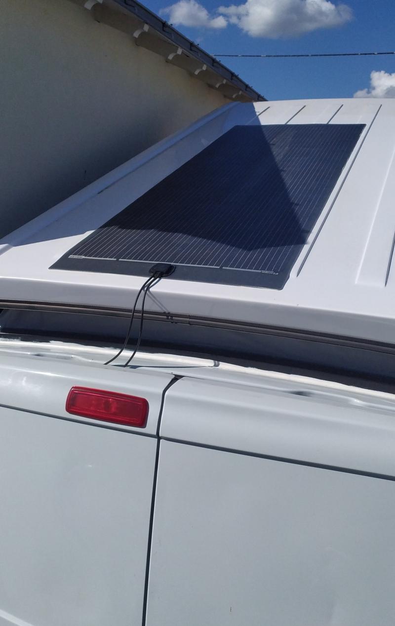
Solar kit: EM MPPT 55/20-BT Solar Regulator / 280W black solar panel with By-pass diode junction box and 1.5 m cable with MC4 termination
Link: https://www.h2r-equipements.com/kit...neau-solaire-souple-perc-flex-280-w-noir.html
4s 12v 150ah battery with home assembly.
Link: https://fr.aliexpress.com/item/1005...t_main.10.2a495e5batQTDq&gatewayAdapt=glo2eng
BMS 60A, LiFePo4 4S 12V BT: https://fr.aliexpress.com/item/1005...st_main.5.2a495e5batQTDq&gatewayAdapt=glo2eng
=> The assembly was done with an electrician. We are missing a fuse dedicated to the solar panel (which we will put soon).
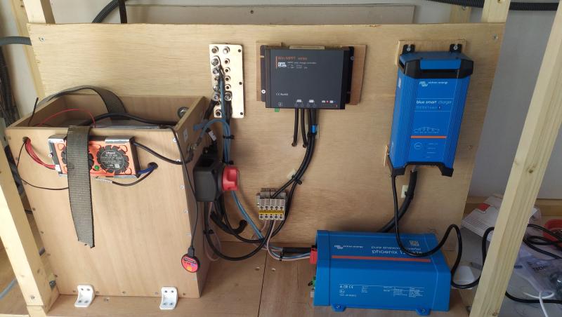
Here is a photo of the assembly:
My observations:
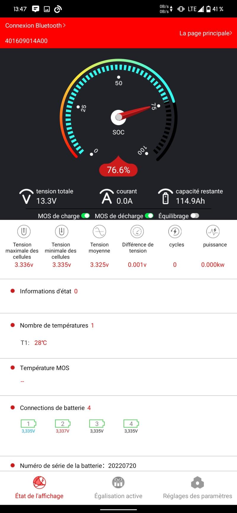
- According to the application of the MPPT, I see many Watts which are generated by the solar panel, I have a quite correct voltage/amperage but nevertheless, I do not see anything passed at the level of the battery (I should see ampere "courant", but it remains at 0. When I recharge via the 15A mains charger, I see 15.2A and I note that the percentage of the battery increases).
We tested the voltages with a voltmeter, they match to what we can see on the MPPT application.
I'm stuck and I need a hand. We thought there was a problem with the + block, but we rechecked the (+) and RAS on it, connection was OK.
- I downloaded the manual to understand the meaning of the LEDs on the MPPT, and it seems correct to me: SOC3: "battery between 50-90%"; quick flash "MPPT Charge"; Blue LED: "Battery is normal"
I have one last thing to do, unplug everything to leave only the battery + bms + solar panel ... I'll test it tomorrow afternoon.


If you have an idea...I'm in !, thank you")
I stuck on a (stupid) battery charging problem with my solar panel. Indeed, even in direct sunlight, the battery does not recharge. When I connect the mains charger (15a), it works on the other hand, it charges correctly and I see it via the battery application (bms).
Here are the components that make up my setup:
Solar kit: EM MPPT 55/20-BT Solar Regulator / 280W black solar panel with By-pass diode junction box and 1.5 m cable with MC4 termination
Link: https://www.h2r-equipements.com/kit...neau-solaire-souple-perc-flex-280-w-noir.html
4s 12v 150ah battery with home assembly.
Link: https://fr.aliexpress.com/item/1005...t_main.10.2a495e5batQTDq&gatewayAdapt=glo2eng
BMS 60A, LiFePo4 4S 12V BT: https://fr.aliexpress.com/item/1005...st_main.5.2a495e5batQTDq&gatewayAdapt=glo2eng
=> The assembly was done with an electrician. We are missing a fuse dedicated to the solar panel (which we will put soon).
Here is a photo of the assembly:
My observations:
- According to the application of the MPPT, I see many Watts which are generated by the solar panel, I have a quite correct voltage/amperage but nevertheless, I do not see anything passed at the level of the battery (I should see ampere "courant", but it remains at 0. When I recharge via the 15A mains charger, I see 15.2A and I note that the percentage of the battery increases).
We tested the voltages with a voltmeter, they match to what we can see on the MPPT application.
I'm stuck and I need a hand. We thought there was a problem with the + block, but we rechecked the (+) and RAS on it, connection was OK.
- I downloaded the manual to understand the meaning of the LEDs on the MPPT, and it seems correct to me: SOC3: "battery between 50-90%"; quick flash "MPPT Charge"; Blue LED: "Battery is normal"
I have one last thing to do, unplug everything to leave only the battery + bms + solar panel ... I'll test it tomorrow afternoon.
If you have an idea...I'm in !, thank you


