diy solar

diy solar

Solar rv electrical system - final checks

DerpsyDoodler

Solar Addict
Joined
Jan 10, 2021
Messages
2,246
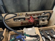
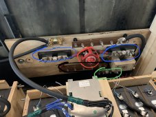
Going through the final checks of my electrical system. Ive attached some diagrams.

i should note, by design, the chassis system has some circuits that use chassis as a return path. No house systems do this.

Inverter is a samlex evo 4024.

Feel free to ask for any missing information. I will be happy to answer questions.

Are there any safety concerns with this design? How should I mitigate them?

These are the questions I am asking.

Thank you!

121A1480-7AAF-4F37-9877-53F8786A93B6.png

E8840EF4-554D-42B0-9B25-56695A4E4BC8.png
 
In my system, the Class T fuse is immediately downstream of the battery, then the disconnect switch. You have it reversed. The fuse should be as close to the battery as possible.
 
In my system, the Class T fuse is immediately downstream of the battery, then the disconnect switch. You have it reversed. The fuse should be as close to the battery as possible.
Sorry for the confusion. I may not have made it clear enough. I have 2x 24v batteries connected in parallel. each 24v battery is protected immediately with a 200a fuse, then goes through the disconnect (dual circuit 300a switch). the switch feeds the positive bus bar. positive bus bar is connected to a 350a fuse via 1/4”x3/4” copper bar. the fuse then feeds the inverter.

positive bus bar is on the bottom, in the attached pic.
 

Attachments

  • 089929B0-FCD4-495A-A8FC-1DBB7E099B74.jpeg
    089929B0-FCD4-495A-A8FC-1DBB7E099B74.jpeg
    275.5 KB · Views: 12
In my system, the Class T fuse is immediately downstream of the battery, then the disconnect switch. You have it reversed. The fuse should be as close to the battery as possible.
For better clarity i marked up the picture.

circled in blue are the 200a class t fuses (note the empty lugs on the outside of each, batteries arent connected yet).

circled in red is the dual circuit disconnect (each circuit capable of up to 300a, and each fused at 200, as previously stated).

circled in black is the positive bus bar.

circled in green is the 350a class t fuse.

Just FYI, the button on the face of the wooden mount is a precharge circuit. 25ohm 50 watt resistor, momentary push button switch rated for 5a and fused at 5a. realistically should never see more than about 1a through that circuit. The button lights when pressed, otherwise remains unlit.
 

Attachments

  • EC0515B8-4E3C-4A2D-9D78-FBB9274A5D8E.jpeg
    EC0515B8-4E3C-4A2D-9D78-FBB9274A5D8E.jpeg
    622.3 KB · Views: 5
Powered up the inverter for the first time, today and went through some checks and initial configuration. all went as planned! took it a step further and plugged into shore power. shore power circuit worked exactly as designed. all went as planned. Turned on AC main, and turned on the 20a circuit for the newly installed a/c system. powered up the ac, ran initial tests, and now have air conditioning in the RV. once again, all went as planned. I am thrilled!
 

diy solar

diy solar
Back
Top