diy solar

diy solar

Solar Sea Kayak

Obi wan

New Member
Joined
Jan 25, 2020
Messages
5
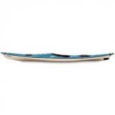
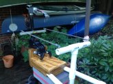
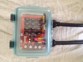
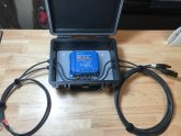
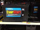
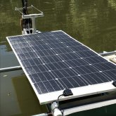
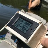
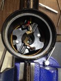
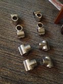
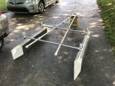
Over the last few years I've been tinkering with my sea kayak by adding an electric trolling motor, marine battery, Renogy 160 watt marine solar panel Victron 75/15 MPPT charge controller. I rebuilt the 28lb thrust Minn Kota trolling motor with a higher efficiency prop and replaced the old resistor speed selector with a pulse width modulation speed controller. I build a tiny console with the variable resistor to the PWM unit and added a power meter for keeping track of my battery's power consumption in the cockpit. I keep upgrading its components every chance I get and now I trying to build a large lithium battery to replace the marine deep cycle lead acid battery. Learning from Will on which batteries would be affordable and provide better range beyond my current configuration. 15.JPG
 
Very nice!
I have a couple of sea kayaks and I've been musing about doing something like that for a few years as well.
How about providing some more details? I'd be interested in knowing; what does your motor draw (before and after mods), how far can you go on a charge? I guess it's like an ebike - it all depends on how much you help.
Seems like a good application - it's summer, the sun is high, and there's no shade.
And if there's shade you've got bigger problems!
So the kayak is an 18ft Perception Latitude. Its really a special kayak in that it has a real rudder integrated into the hull that is steered by a cable system that goes to a set of pedals mounted on top of the foot pegs in the cockpit. This allowed me to build an aluminum frame to hold the trolling motor on a transom then attach to the rudder's shaft with an extension to a T bar that I attached a pair of stainless steel push pull rods with small tie rod ends on each end. So when I press a steering pedal with my foot, it turns the rudder and the trolling motor in tandem. The small 28lb thrust trolling motor has been tweaked with a Honda 2hp outboard prop adapted to it for better efficiency over the standard Minn Kota props made for cutting thru weed beds in the river. The motor was disassembled and had its bronze bearings re greased and the motor's armature cleaned up and the wiring from the motor brush block was increased in size from a 12 gauge to a 10 gauge fine stranded copper wire with silicone insulation. The head of the trolling motor was taken off and replaced with an water tight electrician's 90 degree elbow and an Anderson plug installed for connecting to a Pulse Width Modulation speed controller. The PWM speed controller is mounted inside a Lexan GSI waterproof storage box. All the cables in and out of it are thru water tight glands. From the speed controller, there was a variable potentiometer that controls the speed to the trolling motor. I extended that variable speed potentiometer about 6ft up to the cockpit to a small water tight PVC box for easy access via a 9 conductor cable. This allowed the PWM speed controller to remain near the trolling motor in the rear hold of the boat to keep the DC power wires close to the trolling motor and battery to reduce power loses. The battery is a 100 ampHour Marine deep cycle battery has a 50 amp circuit breaker mounted on it. Both are in the rear dry storage hold in the rear of the kayak along with the PWM speed controller and a Victron 15/75 MPPT Charge Controller with Bluetooth mounted inside a Harbor Freight Pelican Box with its wires entering and exiting thru water proof glands to keep it totally water tight. The Victron then connects to a Renogy 160 watt semi flexible solar panel that sets in a very light weight aluminum frame that setting on top of the main aluminum frame that has the motor transom and outriggers for pontoons. In that small water proof PVC box with the potentiometer, I installed a Power Meter that receives a voltage drop across a shunt resistor installed back in the Lexan GSI box. The shunt resistor sends its voltage drop values thru a pair of wires in the 9 conductor cable. The speed pot uses the other 7 conductors in that 9 conductor cable. Everything that is electrical is 100 percent water tight. The marin
 

Attachments

  • product_78724.jpg
    product_78724.jpg
    1.5 KB · Views: 15
  • 2018-05-19 002 2018-05-19 001.JPG
    2018-05-19 002 2018-05-19 001.JPG
    87 KB · Views: 17
  • 2017-12-03 001 2017-12-03 001.JPG
    2017-12-03 001 2017-12-03 001.JPG
    87.1 KB · Views: 17
  • 11.JPG
    11.JPG
    73.8 KB · Views: 15
  • 2017-09-13 001 2017-08-14 001.JPG
    2017-09-13 001 2017-08-14 001.JPG
    58 KB · Views: 15
  • 14.JPG
    14.JPG
    136 KB · Views: 16
  • 2018-07-19 002 2018-07-19 007.JPG
    2018-07-19 002 2018-07-19 007.JPG
    91 KB · Views: 17
  • 2018-05-19 003 2018-05-19 001.JPG
    2018-05-19 003 2018-05-19 001.JPG
    139 KB · Views: 16
  • 1.JPG
    1.JPG
    190.4 KB · Views: 15
  • 8.JPG
    8.JPG
    119.6 KB · Views: 13
On the performance of the solar kayak, it range is about 20 miles on a sunny day with the 160 watt solar panel replacing my power being consumed at about a 50% rate of consumption. The top speed is about 6 mph. This will result in the battery voltage dropping to about 11.5 volts before it is considered to be too low to use any further. When running it on the Kentucky River, I try to take breaks at every sand bar and creek I come across to allow the battery to recover a bit from running it at full speed. When its running, its is completely silent and clean which are the best things about this boat. When I first built this boat, it had the old resistor 5 speed selector switch that basically wastes off the power in the form of heat when reducing speed. When I replaced that resistor 5 speed switch with the PWM speed controller, I gained about 26 percent in efficiency. So old top speed was drawing about 28 amps and the new PWM speed was drawing about 20 amps to reach 6mph. The charge controller was upgraded from an inexpensive PWM charge controller to the Victron 15/75 MPPT with Bluetooth. The original frame was build out of PVC pipe with a wood core. That first generation was inexpensive and was done to prove the concept before building the frame out of aluminum. The joints are now aluminum Hollaender railing connecdtors and aluminum pop riveted plates and 1 inch aluminum tubing. The pontoons added the additional flotation to offset the added weight of the frame, battery, motor, controls. Eventually I plan to replace the lead acid marine battery with something similar to a Battle Born Lithium Phosphate battery. This will greatly increase my range while reducing the weight. Possibly from there I will construct a light weight set of pontoons to further lighten the boat.
 
Yes, I'm familiar with the pedal rudders. I have a similar system.
1579988706198_1579988704491_20200125_151535.jpg
It's a little hard to see as its hanging from the ceiling of my garage for the winter.
Do you think mine is suitable for a similar conversion?
 
Looks great! I'm using the exact same PWM (Drok) for my 36v 101 lb Riptide I-pilot. I got the motor practically free because the control boards (speed and steering) were fried. I now control the steering with a DPDT toggle switch. In my first few tests I noticed the PWM getting hot above 15 amps, so I added a fan and it's been working great. I'm surprised you are getting away without the fan and with it in a sealed box, but I guess on a kayak getting it wet is worse that getting it hot.

I've got another 80lb 24v Riptide with a bad controller I'm about to do the same thing to.
 
Last edited:
I have a couple of sea kayaks and I've been musing about doing something like that for a few years as well.

Many years ago I added a 30lb MinnKota to my kayak. I found a kid's aluminum razor scooter in the trash and stripped it for the folding steering mechanism. With the "forks" removed, the motor's shaft slid into their place and rode on the bearings. The stock plastic mount was not used. Then, a simple pull cord could pull the motor clear out of the water when paddling or going over obstacles (the stock mount would allow the motor to drag in the water). The aluminum base of the scooter (part of it anyway) was easy to bolt onto the kayak. It didn't have a rudder, so the steering was done through a single push-pull cable (I think I used an old shift cable from an automatic car transmission), going from the motor to a little lever (car console PRNDL shifter) between my legs.

I get my best inspiration from the trash heap :).

spark_fold.jpg
 
Last edited:
Many years ago I added a 30lb MinnKota to my kayak. I found a kid's aluminum razor scooter in the trash and stripped it for the folding steering mechanism. With the "forks" removed, the motor's shaft slid into their place and rode on the bearings. The stock plastic mount was not used. Then, a simple pull cord could pull the motor clear out of the water when paddling or going over obstacles (the stock mount would allow the motor to drag in the water). The aluminum base of the scooter (part of it anyway) was easy to bolt onto the kayak. It didn't have a rudder, so the steering was done through a single push-pull cable (I think I used an old shift cable from an automatic car transmission), going from the motor to a little lever (car console PRNDL shifter) between my legs.

I get my best inspiration from the trash heap :).

spark_fold.jpg
That's a great idea! I threw one away after no one wanting it and my inability to come up with any idea to make with it. Doogh!
 
Does the shaft of the motor pass through the hull? How do you seal it?
That was my 2019 Hobie Outback, before I traded it for a Taylor guitar. The hole goes through the hull and is where the Mirage pedal drives goes through. I just got a little lazy sometimes when I felt like trolling so I adapted the electric motor to the pedal drive area. It required shortening the shaft and modifying its intended purpose but I just followed a path that had been walked before.
 
Back
Top