diy solar

diy solar

Sure could use some help quickly! Aimes inverter charger

tmorrgold

New Member
Joined
Oct 13, 2019
Messages
45
Does anyone know how to reset an aims inverter/charger? I have a 24 volt, 2000 watt inverter charger. I have been using it for several days with no issues, right now hooked up to shore power. It just clicked and shut down. When I turn it on, the green light is on for "inverter mode" and it is running on shore power. But no a/c power is coming out, not to my breaker panel and not from the outlet on the back of the unit. Of course it happened a few minutes after Aims tech support left for the weekend and I an't find anything online or in the manual.

I'm kind of desperate. Any help would really be appreciated. Thanks!
Linking the inverter/charger will help us help you.
 
Do you mean the model? I think there is only one, but the actual model is aims picoglf 2k model.
 
If you have a dvom check to see what the dc voltage is at the inverter leads.
Also check to see if mains voltage is in spec.
Report back.
 
Thanks, I appreciate the help. I am just hoping someone can tell me how to reset it for tonight, as it's 100 degrees and difficult to sleep, and I'm hoping that is all I need to do to get it up and running again. Obviously on the likely chance that doesn't fix anything, I will have to dive deeper into diagnostics. But that can wait until tomorrow.
 
Reading through the manual in the dark with a flashlight, I finally found a schematic showing the a/c circuit breaker and "push to reset"!! And it worked. :)
 
Yep, "push to reset" will do it, but a more important question is: why did it trip the breaker? It probably should not.

I had a similar issue with my Aims system installed in my solar/lithium camper trailer. When I originally installed my Aims inverter, I wired it directly to shore power, so I could use its Transfer Switch capability. But if I ran more than 2kW, the inverter breaker would trip even if it was not inverting.

There are several problems with this. Biggest issue is that wiring it like this effectively downgrades your 30-amp service to only 20-amp, because that is the limit of the Aims inverter. Also, the Aims inverter runs HOT, when pushing close to 20 amps, but a service panel would not break a sweat.

This is counter-intuitive, because when on shore power, the transfer switch sets the inverter to charge-mode, and the 120V power flows through directly to the outlets, without involving the inverter or battery. You'd think that the 2000W limit would not apply. But as you found out, there is a breaker in the inverter itself, and you should never run more than 20A through it, either on shore or battery power. The relays and internal wiring are rated for 20A only, and above that, it will cut off.

To fix this, I had to eat some humble pie, start over and re-wire the whole thing. Here's how I did it:
1. 30A service comes in to the breaker panel, as before.
2. One 20A circuit goes from the panel to the inverter.
3. Those circuits that should never run on inverter (AC unit, electric hot water heater, 2-way fridge on 120V AC mode) were wired to ONLY run when on shore power. (That's ok, because when on battery, the AC is too powerful and won't run, and the other two can run on propane)
3. All the other circuits, that work on inverter are connected to a sub-panel, which provides a 15A breaker for each inverter circuit. The neutrals are NOT connected to each other (otherwise you'd trip a GFCI breaker if shore power was on GFCI)

Now my inverter never trips its 20A breaker, no matter what I plug in, which is great because accessing the inverter requires disassembly. It's all properly protected by the breaker panel, which is easily accessible to the user.

I hope that helps.
 
Thank you so much for that explanation! That is exactly what my problem is/was and your post really helped me understand how the system works.
 
I'm so happy my post helped.

Here's another 'trick' - How to you install a 'sub-panel' in an RV? An electrical box is a huge heavy item - do I really need all that?

I bought the smallest Square-D electrical box at the homestore (HD/lowes) It is simply a metal box with a busbar inside. The smallest handles 60 amps, and has room for four 15-amp half-size breakers in the same space as 2 regular breakers.

I removed the busbar, and discarded the metal box. The busbar was mounted inside the plastic housing where the other breakers are located. Then, I wired it to take the output of the inverter and distribute the power to all the inverter circuits.

All of this is absolutely necessary, to properly incorporate an inverter. It's electrician grade stuff, but totally doable for the average DIYer.
How did you handle chassis bond?
Do you have provision for shore power?
If yes how did you handle the neutral/ground bond issue?
 
When it comes to neutral-ground bonding, there is a 'correct' way to do it, and an incorrect way. A lot of RV electrical problems you read about (on forums such as this one) are related to grounding.

Typically, there is one place where neutral is bonded to ground, and it's where the service comes into the main panel. For a residence, it's bonded at the main panel, where the ground is connected to a copper rod, driven into the earth. But for an RV, there should be no bond. The 120V ground should be 'floating'. Then, when you plug into shore power, you get the neutral-ground bond from the shore power's bond. Similarly, if you plug into a generator, then the generator should have the bond, same as with shore power.

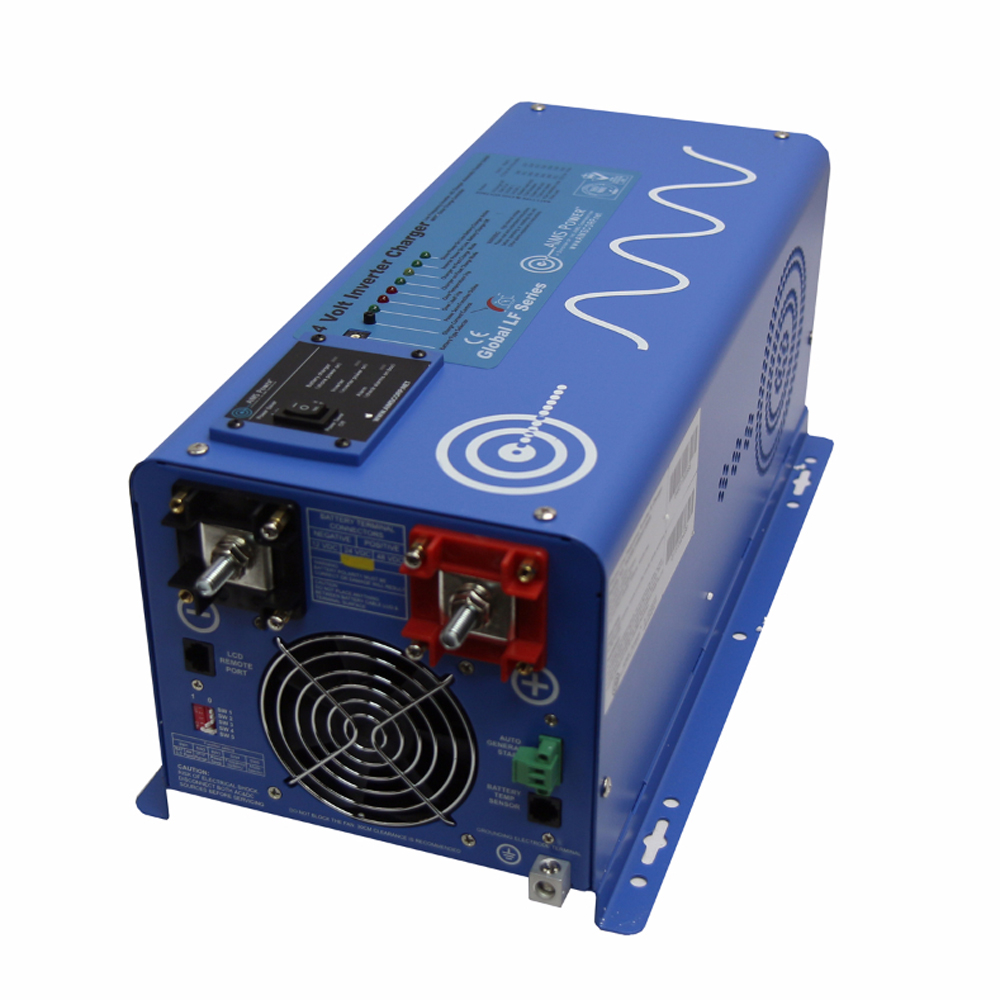
That's how things should be with a standard trailer. Now when you introduce the Aims inverter, with an automatic transfer switch, the bonding requirements are different. When on shore power, you use the bond in the service panel, and when inverting, the inverter should have its own bond. The Aims inverter does this! Read the Aims user guide (and read it again) as it explains this very clearly. The inverter bond is configurable to create a bond or no bond when inverting, per your electrical requirements. If there would be no other bond when inverting, then use the Aims inverter's bond. This is how I have set it up.

To see if your bonding is set up right, connect the trailer to shore power on a household CFGI outlet. If it trips, then you probably have a grounding issue.

As for the 'chassis bond' - that's something else. The 0-Volt DC ground should be bolted to the chassis in one place, to avoid ground loops that cause audio noise. This doesn't need to change, and should be bonded already, but best to ensure that it is connected in just one place, with a really solid ground using 6-gauge wire.

To summarize, here is how I set it up:
* Shore power comes into RV's 30A service panel, which is floating. A bond is provided by the shore power service, and the trailer takes that bond.
* Inverter is on its own 20A circuit, and all circuits powered by the inverter are on their own sub-panel.
* All the grounds are connected together everyhere, but neutral is left floating.
* The Main and sub-panels do not share a neutral.
* There should be no connection between neutral and ground anywhere in the wiring, but the Aims inverter should be set up to create a bond when inverting, and leave it floating when on shore power.
 
* All the grounds are connected together everyhere, but neutral is left floating.
"UL458-listed inverters have internal automatic neutral-to-ground switching relay. This relay allows for neutral to ground bonding to occur when the inverter is in off-grid DC to AC mode, it also separates neutral from ground at the utility power service if it is connected to a utility hookup. It does so because in mobile power systems, neutral is bonded with ground." --
 
Yes, that's correct.

>>UL1741-listed inverters must allow for the neutral-to-ground bond to only occur at the main AC service panel.
This is how a regular inverter/charger would be, if it doesn't have an automatic transfer switch. For example, a residential solar system with grid-tie inverter.

>>UL458-listed inverters have internal automatic neutral-to-ground switching relay.
This is what the Aims inverter does, and this is what you need for an RV inverter setup.

>>All the grounds are connected together everywhere, but neutral is left floating.
I was referring to the main/sub panel setup. All the grounds are wired together everywhere. Ground is ground. But the neutrals are kept separate between main/sub panels, because if they were tied together, the GFCI would trip, thinking there was a ground fault. Neutrals are thus left floating (not tied to ground) because that is done by either the main service panel (on shore power) or the inverter (when inverting)
 
Back
Top