diy solar

diy solar

Top balancing watt expectations

NCblueridge

New Member
Joined
Jul 31, 2020
Messages
154
Hi everyone. So I have mmy new 4 Lifpo batteries connected in parallel and recieved the inexpensive power supply I bought on Amazon.

The out of the box voltages for the 4 105AH cells were originally:

3.298
3.288
3.248
3.184

After spending some time understanding this new Dr. Meter variable bench power supply (30volt/10amp), I locked the voltage in at 3.65 CV. I then connected my terminals to the respective positive/negatives on the batteries and set the amps as high as they will go.

Voltage is remaining constant but amperage seems to be really low (@3 amps max) and obviously wattage at @12 or less.

I also have my multimeter hooked up and have been checking the values since. It is slowly rising but it seems like it could take days or more before the pack gets to the desired voltage.

2:00pm, 3.297
4:30pm,3.311
9:23p, 3.314

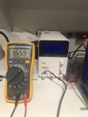
Here's a few pics of the PS and my multimeter attached and my mm I just took.

The PS working:

IMG_2133.jpeg

The current voltage of the bank:

IMG_2134.jpeg

Is this normal for a situation like this - the PS is supposed to go to 10 AMPS but it hasn't moved past @3 amps after hours?


Thanks,
William
 
Pretty marginal condition as received. Those were not "matched" in any way.

You have a very high resistance connection to the PSU for the set voltage limit, hence the disparity between your meter and the PSU. The PSU is hitting its voltage limit and regulating current to maintain it.

The only way you'll get to 10A is if you:
1) set the PSU to a much higher voltage thus removing the "safety".
2) construct new short, beefy leads with ring terminals as a connection. Alligator clips suck.

Example (18awg, 3.314V, 3.13A, 3' leads - does not consider shitty alligator clips):


1597803493450.png
 
Pretty marginal condition as received. Those were not "matched" in any way.

You have a very high resistance connection to the PSU for the set voltage limit, hence the disparity between your meter and the PSU. The PSU is hitting its voltage limit and regulating current to maintain it.

The only way you'll get to 10A is if you:
1) set the PSU to a much higher voltage thus removing the "safety".
2) construct new short, beefy leads with ring terminals as a connection. Alligator clips suck.

Example (18awg, 3.314V, 3.13A, 3' leads - does not consider shitty alligator clips):


View attachment 20264

Thanks, I may just let it run for however long at this point, as long as it doesn't catch the house on fire, I'm in no great hurry. I may \give them a few days and then hopefully they are at closer in individual values at least between them? I plan to charge them fully once I rewire in series and have the (overkill) BMS on.

As far as the batteries being matched fron the supplier, no they sure weren't. These 105 AH lifepo4 batteries were new and purchased as a set from the same aliexpress supplier as featured on a video about building your own pack, they have the smaller terminal nuts.

I did contact the vendor and gave him the voltage of each but he just said they don't factory balance them. I would have figured as new ordered together, they would be similar at least but maybe they pick random ones to send to folks? They also only included 3 f the thin non-copper bus bars so I asked if I could puchase 3 more so I could balance them as was suggested but he never even responded back. Next time I will go with a different vendor and battery set for sure.
 
You can verify my theory by temporarily cranking the voltage way up and continuing to monitor with your voltmeter. It may take an adjustment of both the voltage and current to get there.

Also, while most people are terrified of it, LFP can safely be charged to 4.2V, but there is very little gain (1-3%) in doing so. The occasional trek to 4.2V isn't going to do any damage, but frequent trips will eventually decrease the life of the cells.

You might try taking it up to 4.0 or so and seeing what kind of boost you get.

Other options include:
  1. cutting the wires to as short as you can practically use
  2. stripping the ends of the wires and sandwiching them under the terminal bolts to improve connection.
  3. Using a zip tie to GENTLY pinch the plugs at the unit towards each other can help improve the bullet connection quality.

Thanks, I think I'm going to go with thicker wire with a shorter length and connect directly to the terminals on both the power supply and battery set.
 
You can verify my theory by temporarily cranking the voltage way up and continuing to monitor with your voltmeter. It may take an adjustment of both the voltage and current to get there.

Also, while most people are terrified of it, LFP can safely be charged to 4.2V, but there is very little gain (1-3%) in doing so. The occasional trek to 4.2V isn't going to do any damage, but frequent trips will eventually decrease the life of the cells.

You might try taking it up to 4.0 or so and seeing what kind of boost you get.

Other options include:
  1. cutting the wires to as short as you can practically use
  2. stripping the ends of the wires and sandwiching them under the terminal bolts to improve connection.
  3. Using a zip tie to GENTLY pinch the plugs at the unit towards each other can help improve the bullet connection quality.
On each of my 8 cell, 24v 280aH packs (4) so far, it was clearly going to take months to years to get them to 3.65v when set that way on the charger.
I only got them up to a "top balancing" point when I upped the voltage to 3.8v. Then it only took a few days... lingering at first, before rising quickly ay the end. Each time I cought it before the amps actually got to 0.
So 3 of my 4 packs have been technically top balanced to 3.7v or 3.8v...the 4th is charging now. I'm not sure the feedback I'd get on my approach, but I'm sure I saved myself years of my life. On one pack literally left it on that charger for almost 4 weeks, with only nights off to rest every few days, and only got a nominal voltage increase. Turned it up some and boom, done. Not sure why, but the way it went.
Glad to hear I probably didn't hurt anything.
 
I see exactly the same voltage gap between my cheap psu and battery banks. The gap was 0.3v and that drives about 4A charge. The picture below shows me getting bored and upping the voltage but the gap is similar. I thought crappy high resistance wiring was the problem but now I’m using 10AWG with hydraulic crimps and the voltage difference is the same.

If you think about it there has to be a voltage drop to make the current flow and charge the cells, but that implies a cell resistance of .3v/4A = 0.075 ohms. I thought Internal resistance on these cell was lower and the specs show it. There is another way to measure resistance though so I’ll post a question somewhere about how to think about that
 

Attachments

  • 19D56C20-5A1F-4BFE-895D-A234C487C2AF.jpeg
    19D56C20-5A1F-4BFE-895D-A234C487C2AF.jpeg
    81.2 KB · Views: 6
On each of my 8 cell, 24v 280aH packs (4) so far, it was clearly going to take months to years to get them to 3.65v when set that way on the charger.
I only got them up to a "top balancing" point when I upped the voltage to 3.8v. Then it only took a few days... lingering at first, before rising quickly ay the end. Each time I cought it before the amps actually got to 0.
So 3 of my 4 packs have been technically top balanced to 3.7v or 3.8v...the 4th is charging now. I'm not sure the feedback I'd get on my approach, but I'm sure I saved myself years of my life. On one pack literally left it on that charger for almost 4 weeks, with only nights off to rest every few days, and only got a nominal voltage increase. Turned it up some and boom, done. Not sure why, but the way it went.
Glad to hear I probably didn't hurt anything.

Positive from me.

I see exactly the same voltage gap between my cheap psu and battery banks. The gap was 0.3v and that drives about 4A charge. The picture below shows me getting bored and upping the voltage but the gap is similar. I thought crappy high resistance wiring was the problem but now I’m using 10AWG with hydraulic crimps and the voltage difference is the same.

If you think about it there has to be a voltage drop to make the current flow and charge the cells, but that implies a cell resistance of .3v/4A = 0.075 ohms. I thought Internal resistance on these cell was lower and the specs show it. There is another way to measure resistance though so I’ll post a question somewhere about how to think about that

It's absolutely, positively not the cells unless you have grossly horrific cells worse than anything ever posted on the forum. Your cells are also in parallel, thus your effective circuit cell resistance is 1/nth the resistance of a single cell (n=# of cells).

Are you still using the bullet connectors? Stock ones are shite. You're also dealing with the internal resistance of the PSU.

IMHO, set voltage to 4.2V and monitor with a separately attached VM. Zero chance you'll damage the cells.
 
The issue is the power supply. I shorted the psu output and got 5.25A and 0.52v on the psu screen, for 0.1ohms internal resistance. resistance of the battery too low to measure with this equipment. I think these are the same pretty good 280ah cells that are around. They discharged to full rated capacity after I balanced but I’m stuck until my inverter/charger arrives and I can use meaningful C rate closer to the EVE testing protocol.
 
Positive from me.

It's absolutely, positively not the cells unless you have grossly horrific cells worse than anything ever posted on the forum. Your cells are also in parallel, thus your effective circuit cell resistance is 1/nth the resistance of a single cell (n=# of cells).

Are you still using the bullet connectors? Stock ones are shite. You're also dealing with the internal resistance of the PSU.

IMHO, set voltage to 4.2V and monitor with a separately attached VM. Zero chance you'll damage the cells.


Yes, I've bumped it up, I'm here to monitor it also. When I get closer I'll drop it back down to 3.65. I am using a set of much thicker connectors now.
 
Where are you guys getting the upgraded connectors? What specs?

I have the standard wires that came with my power supply. Not wimpy, but not beefy either. I have some plugs that fit, but they're leftovers from some project years ago and I have no idea if they are suitable.
 
Where are you guys getting the upgraded connectors? What specs?

I have the standard wires that came with my power supply. Not wimpy, but not beefy either. I have some plugs that fit, but they're leftovers from some project years ago and I have no idea if they are suitable.

You make them yourself. Anything that doesn't catch fire or get excessively hot is arguably suitable, but with these cheap "lab" power supplies, the low 3.65-ish voltage is susceptible to voltage drop due to internal and wiring resistance. Best to compensate by setting to something higher than 3.65 but no higher than 4.2V.
 
I made mine. 10 gauge and a solid crimp will do it, although bare ends will work on the power supply end. Funny story: I took the psu leads off and used them to do a quick discharge test on my cells. They got hot enough one clip fell off. When I checked I saw that some insulation had melted and the alligator clip fell off the wire because the insulation was holding it in the crimp. It had been crimped on with at most a quick slice across the lead. It’s crimped metal to metal now
 
I was expecting to make them myself. Wire I have plenty of. The connectors that plug into the power supply is the unknown. I think they're called banana plugs but I don't know what size is appropriate. If it's the wire that is important, will any banana plug do?
 
You make them yourself. Anything that doesn't catch fire or get excessively hot is arguably suitable, but with these cheap "lab" power supplies, the low 3.65-ish voltage is susceptible to voltage drop due to internal and wiring resistance. Best to compensate by setting to something higher than 3.65 but no higher than 4.2V.
I don't know about the 4.2v talk, that scares me a bit. But I was successful using 3.8 four times. It went pretty quick with that setting, no change to the factory leads.
 
Back
Top