diy solar

diy solar

Totally confused re copper bus bar ampacity

bds70

New Member
Joined
Dec 2, 2023
Messages
197
Location
Queensland
I have 4 x 12v 280AH batteries in parallel. I also have 2 3000w inverters that the batteries supply power to. Calcs say max amp draw could be 586amps.
I want to use a 20mm X 10mm copper bus bar connecting all 4 batteries to the lynx distributor.

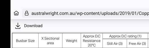
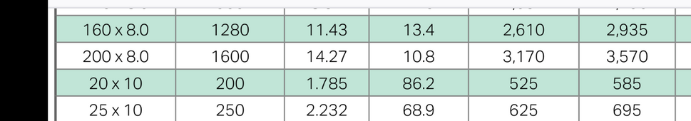
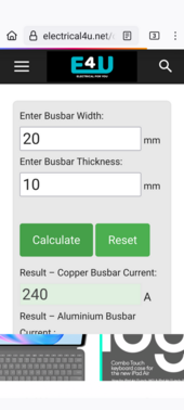
However according to "off grid garage" and a few web sites that size bar can only handle 240amps max, but another trade website has tables showing DC rating (free air) at 585amps.

See attached screenshots. Please can someone clarify.
 

Attachments

  • Screenshot_20240718-195111.png
    Screenshot_20240718-195111.png
    91.3 KB · Views: 9
  • Screenshot_20240718-195049.png
    Screenshot_20240718-195049.png
    62.2 KB · Views: 9
  • Screenshot_20240718-194731.png
    Screenshot_20240718-194731.png
    173.7 KB · Views: 9
Yeah, I think the blanket "1.2A per mm2" which leads to the 240A rating is rather conservative and assumes a circular or at least square cross section (smallest surface area for cooling).

But if you have a wider, thinner bar of the same CSA it will have a larger surface area which would allow better cooling and thus more capacity.

The table at https://www.australwright.com.au/technical-data/advice/copper-busbar-rating/ has a 200mm2 bar rated at anything from 585A for 20mmx10mm to 740A for a 50mmx4mm bar.
 
3000w 12v inverters are not a wise purchase. Dealing with >150 amp connections require a lot of attention to details.

You will typically have greater resistance in the bus bar to battery terminal compression surface contacts then the bus bar alone.

The nickel plating raises the net copper core bus bar resistance about 20% but is necessary to prevent copper-aluminum intermetallic corrosion which eats pits into the aluminum battery terminal surfaces.

Be careful of getting cheap nickel-plated brass core bus bars which are over 3x the resistance.

Bus bar connection testing.png
 
Last edited:
I've been using that AustralWright table but this site
gives quite a bit of variation. And you are correct, some sites come up with 240A for that size
Note free air and bar spacing temperature rise etc. Also some charts are AC current only and mention skin effect at varying temperatures. No skin effect on DC
If you have some kind of protective guard over them you have heat build up without forced airflow. It's all a bit messy
I'm coming at it from a different direction...
OLEX says that their 95 sqmm cable can carry about 290A AC and that's with it sheathed in PVC. So I that sort of suggests that you could use a 200 sqmm bar but I'd give it a 50% fudge factor to allow for heating.
40mm x 8mm maybe
 
3000w 12v inverters are not a wise purchase. Dealing with >150 amp connections require a lot of attention to details.

You will typically have greater resistance in the bus bar to battery terminal compression surface contacts then the bus bar alone.

The nickel plating raises the net copper core bus bar resistance about 20% but is necessary to prevent copper-aluminum intermetallic corrosion which eats pits into the aluminum battery terminal surfaces.

Be careful of getting cheap nickel-plated brass core bus bars which are over 3x the resistance.

View attachment 229449
This is not the cell to cell bus bar I am talking about. It's a main bar from battery to battery. So I am not sure that what that chart is in relevance. Can U elaborate please.
 
Rough calculation 50mm by 8mm in free air. This is calculating backwards from 800amps and 50mm wide using ampacity of copper in free air , so on standoffs where the heat can escape
 
I've been using that AustralWright table but this site
gives quite a bit of variation. And you are correct, some sites come up with 240A for that size
Note free air and bar spacing temperature rise etc. Also some charts are AC current only and mention skin effect at varying temperatures. No skin effect on DC
If you have some kind of protective guard over them you have heat build up without forced airflow. It's all a bit messy
I'm coming at it from a different direction...
OLEX says that their 95 sqmm cable can carry about 290A AC and that's with it sheathed in PVC. So I that sort of suggests that you could use a 200 sqmm bar but I'd give it a 50% fudge factor to allow for heating.
40mm x 8mm maybe
I follow your reasoning and also looked at those tables, but the common imperial sizes they obviously use in the industry didn't match. 40 X 8 would cost 2 arms and 1 leg for sure. But if that's what I need, then that's what I will have to get. Sigh. 🤪
 
Rough calculation 50mm by 8mm in free air. This is calculating backwards from 800amps and 50mm wide using ampacity of copper in free air , so on standoffs where the heat can escape
The way I have built my boxes, each pos/neg terminal is a 2 inch high tensile steel bolt with a nut, as a standoff, the bar on top and nylex nuts to complete it, and allow air to circulate. I am thinking of also putting in two computer fans to constantly blow air across the whole setup as they are in an external steel locker on my bus. My head hurts!
 
Calcs say max amp draw could be 586amps.
I want to use a 20mm X 10mm copper bus bar...
You don't have to design for max amps continuous except if you plan to pull 7500W continuously from inverters.
3/4 x 1/4'' (19x6mm) busbar will take over 400A continuous with a small temperature rise, so don't overdesign for nothing.
 
You don't have to design for max amps continuous except if you plan to pull 7500W continuously from inverters.
3/4 x 1/4'' (19x6mm) busbar will take over 400A continuous with a small temperature rise, so don't overdesign for nothing.

NEC says that will do about 250amps.... my bus bars that are rated 300 amps are bigger than that.
 
NEC says that will do about 250amps.... my bus bars that are rated 300 amps are bigger than that.
Right, NEC.
And the 3/4'' x 1/8'' (50 mm2) motor cables of a Tesla 3 pass 1000A. Is Tesla engineers are all stupid?
At the end, everything is relate to duty cycle and acceptable temperature rise.

One thing I remark on this site is people regularly over design the busbars, but don't attach much importance at contacts as RCinFLA explained.

You will typically have greater resistance in the bus bar to battery terminal compression surface contacts then the bus bar alone.
 
I hear ya, I do.

But I prefer to overdesign a bus bar no more than they cost and meet the NEC since I live here and may be inspected when I do the whole house. The NEC allows for custom made bus bars out of raw copper bar stock which is where I will be leaning.

The major difference is the NEC doesn't want the copper to heat beyond 75c - so there are also ventilation requirements that derate the bus bar depending on where it is installed.

I wonder just as a point of curiosity what the canadian and australian equivalent body has to say on the subject?

Interesting read on the whole subject
 
The NEC allows for custom made bus bars out of raw copper bar stock which is where I will be leaning.
That may not be the case in his country.

I made bus bars too!
I would pull the stock off the rack, cut and punch to the print I was given, tap holes are required and then silver plate them.
I hated the last part because I was really scared of the chemicals ( cyanide )....

But the assembly had to be inspected by ESA for field evaluations or CSA for international customers or other provinces.
This can be a real liability issue


Yup - I noted that

I'll have to go back through my bookmarks but there is at least one copper vendor will cut to length, bend, punch holes, tap and plate them to you specs. Of course there is a charge for all of that and they aren't so cheap but it is a one time cost for the most part.
 
Right, NEC.
And the 3/4'' x 1/8'' (50 mm2) motor cables of a Tesla 3 pass 1000A. Is Tesla engineers are all stupid?
At the end, everything is relate to duty cycle and acceptable temperature rise.

One thing I remark on this site is people regularly over design the busbars, but don't attach much importance at contacts as RCinFLA explained.
Regarding your last paragraph, for the main terminal contacts, is there a common or advised method in the diy world of designing low resistance contacts for the bus bar?
 
Yup - I noted that

I'll have to go back through my bookmarks but there is at least one copper vendor will cut to length, bend, punch holes, tap and plate them to you specs. Of course there is a charge for all of that and they aren't so cheap but it is a one time cost for the most part.
How common are panel shops in the USA and other places?
I mean shops that make large electrical panels, switch gear, MCCs ect.

I find its not that hard to get the materials like from places like that and there still seems to be more than a handful of them around up here at least making the kids of custom electrical equipment you need for manufacturing plants.

You could just buy a length make what you want, get a field inspection done and Bobs your uncle....
Its really not very hard to drill and work as long as you use the correct lubricant.
Fitting is important...
Learn to draw file make things flat...


I used to impress the hell out of the young guys at work with my vice work.
I could do stuff most guys thought you need to go to a machine shop for.
With regards to bus work there was a time when you had to do some fitting to make sure you had a good connection between joints on punched bus work.
I don't think I have seen anyone bother to fit anything nice in a long time but for this application where you want really good connections I think its something people should consider.
 
There is a problem with bending a copper bus bar. It causes a hard spot and that in turn is a hot spot when current is flowing. They avoid this by annealing it after working it. Minimum turn radius is usually 2x the thickness of the bar. That book on copper bus bars in resources covers a lot on the topic.
 

diy solar

diy solar
Back
Top