diy solar

diy solar

Two 12V LiFePo4 batteries in Series one shows Reverse Polarity

That’s one of the things I’m trying to figure out with my posts -what should the voltage measurement be across a battery with a BMS that has “disconnected”?

I assumed it would read 0, but I’m finding info online that suggests some could read as high as +6/7 Volts, and regardless of what it reads, some have suggested it shouldn’t be trusted and the value is just arbitrary.

That is what I see when the BMS disconnects on mine. But as also noted, it can't really supply any meaningful current.
 
That’s one of the things I’m trying to figure out with my posts -what should the voltage measurement be across a battery with a BMS that has “disconnected”?

I assumed it would read 0, but I’m finding info online that suggests some could read as high as +6/7 Volts, and regardless of what it reads, some have suggested it shouldn’t be trusted and the value is just arbitrary.

Remember once I put a load on the battery that has that low resting Voltage of +13.18 it will drop down to +6.5V or so, but strangely it will continue to let me pull power from it with an 12V LED dome light.

Strange indeed.

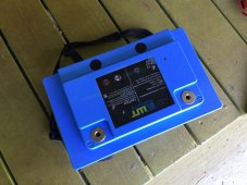
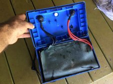
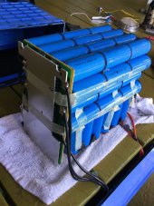
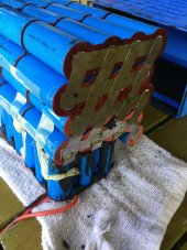
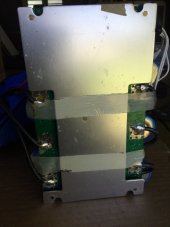
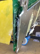
Regarding the cases, they are quite a bit nicer than most I have seen in videos of tear downs, very similar to the Valence XP except the boards aren’t separately accessible, but I think I can get into it without too much carnage. Hoping they used a butyl tape instead of glue.

I have been in contact with the manufacturer. I bought them direct and had them built to order with the BMS configured for high discharge rates.

I let them know the first time this happened some months ago, and contacted them last week to let them know it has happened again, and asked some specific info about the BMS and how it should behave, Waiting to hear back now.

I think I am approaching my Warranty, but you know living in Hawaii we are kind of on our own, so I may have to see if I could at least get a replacement BMS if in the end I suspect it to be at fault.

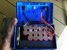
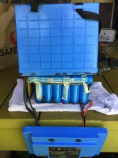
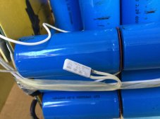
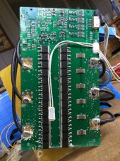
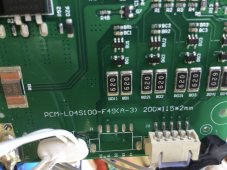
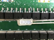
Hoping if/when I get it opened up I can identify the brand of BMS, and with any luck there might be a Bluetooth module already built in that I can try to communicate with. Other buyers of EWT have opened them up and discovered a full featured BMS.

I wouldn’t be surprised if in the end I find a fried Gecko or a colony of those pesky red ants inside ?
Wait a minute, you have those little fire ants on your island? That sucks, they reduced the quality of life majorly for us jungle dwellers.
 
Wait a minute, you have those little fire ants on your island? That sucks, they reduced the quality of life majorly for us jungle dwellers.

Not the super nasty fire ants that bite, but the big pesky red ones. I am convinced they must be robots, probably running on lithium ion. The way they pick up their dead and haul them off, I’m convinced they must be taking them back to the shop for rebuilding ?
 
So I heard back from the battery manufacturer today. You always have to take responses with a grain of salt between the language barrier and the relaying of technical questions sent to a salesperson who then asks an engineer, who then relays the answer back to the customer. It took a few tries and rewording, but I think I finally got some accurate info.

That info is that they program the BMS to disconnect if any cell group falls below 2.5V or exceeds 4.25V.

I am interpreting their response because although I asked about how their BMS works in relation to the 12.8V batteries I purchased, the response I got back from the engineer was about individual cell voltage (they manufacture the 32700 cells) when asked about conditions that cause the BMS to disconnect due to overcharge and discharge.

I was also told that the BMS is not a two-way design and that it should fully disconnect in either situation and not continue to allow charging or discharging until it is reset.

I have attempted to ask/communicate about how the battery would behave in a Serial string with regard to my voltage readings, but I expect this will be too confusing and that I’ll likely not get a meaningful answer.
 
Last edited:
I went ahead and opened the battery up. The box is definitely a better quality than others I’ve seen torn down. Using paint scrapers and putty knives I was able to finally gat the lid off which seals in a double channel/groove. A rubber mallet and multiple scrapers/putty knives did the trick. Then once I got it opened I had to figure out how they assembled it so I could take it apart in reverse. By the looks, it appeared they assembled the whole thing as a brick taped and welded together, then placed it in the box with foam inserted and goop to keep it fixed to the walls. Once I removed the foam pads and cut through the goop, I was able to flip it upside down and the internals came out as a brick.

At first glance I didn’t notice anything too strange. As I suspected, I did find condensation inside, and after cutting the tape and pulling the BMS away, I did see signs of corrosion at the bottom of the board where it rests against the bottom of the box which is where condensation lid collect.

I still need to remove the heat sink from the board for closer inspection, however measuring the voltage of each grouping of cells where they enter the BMS, I get 13.50/13.51V, and when measured at the output of the BMS, I only get 12.6V and it slowly drops as I hold the voltage meter leads to it.

The BMS was acting like it is in disconnect prior to the tear down which the readings seem to indicate as well.
 

Attachments

  • EC716D6C-E7B7-4BCD-B2FB-DAF5671D506B.jpeg
    EC716D6C-E7B7-4BCD-B2FB-DAF5671D506B.jpeg
    249.6 KB · Views: 12
  • 94C3033C-8A99-46EC-8E63-8D100B2EA279.jpeg
    94C3033C-8A99-46EC-8E63-8D100B2EA279.jpeg
    288.5 KB · Views: 12
  • 0B831772-812D-4640-850C-D2A7F3140F72.jpeg
    0B831772-812D-4640-850C-D2A7F3140F72.jpeg
    299.1 KB · Views: 12
  • 7B7379DB-DC03-4977-9D3E-03D6935F4C2D.jpeg
    7B7379DB-DC03-4977-9D3E-03D6935F4C2D.jpeg
    166.3 KB · Views: 13
  • 22638C19-CF26-4AD2-B13D-3204C419F947.jpeg
    22638C19-CF26-4AD2-B13D-3204C419F947.jpeg
    197 KB · Views: 15
  • 50F29653-2620-47A1-B8C0-02D225021C16.jpeg
    50F29653-2620-47A1-B8C0-02D225021C16.jpeg
    202.6 KB · Views: 15
  • 7C0B05D2-69B9-40CD-B081-4AA084F83064.jpeg
    7C0B05D2-69B9-40CD-B081-4AA084F83064.jpeg
    230.9 KB · Views: 14
  • 27A6AEB7-9D54-4969-AB87-4DDFD3CC243F.jpeg
    27A6AEB7-9D54-4969-AB87-4DDFD3CC243F.jpeg
    115.3 KB · Views: 12
  • DFE4BD8D-5AEC-4149-B71C-B0925F65B2B1.jpeg
    DFE4BD8D-5AEC-4149-B71C-B0925F65B2B1.jpeg
    126.4 KB · Views: 12
Last edited:
Heatsink removed from BMS. Definitely evidence of moisture damage primarily along the lower edge of the board and the components (the two MOSFETs in particular) located there where it rests at the bottom of the box, but there are other components further up the board that don’t look to be thrilled about the environment they live in either. Also spotted the beginning of a trace failure on the board itself from moisture wicking up the bottom edge with it starting to lift off the board.

The good news is it looks to be a commonly available Smartec BMS, however I am displeased to discover the BMS is only good for 100A continuous discharge. I had requested and paid for higher rated BMS’s. Now I’m wondering what’s inside the other battery.

That said, I could pull 120A continuous without any issues, so I assumed they had built them with the bigger 150A BMS per my request/order.

Here’s a link to Smartec’s offerings. I see they have a Bluetooth line, but it only goes up to 100A.


The BMS appears to be measuring stacked voltage from the pack in that there are only 4 wires, one a ground soldered to the back of the bank, and then the other 3 wires are placed at the midpoints between the groupings of cells. So when you measure at the individual wires coming off each group, you get 3.37V, 6.75V, 10.13V, and 13.51V.

Battery is a 4S configuration of 17 6000mah cells in parallel for 102ah of capacity.

Looks like it wouldn’t be too hard to pull individual cell voltage from the board and run it eternally where one could test with a voltmeter. The board is already set up for reporting that data, and I think at one time there was an optional Bluetooth module that connected to the open spot that pulls from the main connector plug.
 

Attachments

  • BF94B298-3BFA-4CEA-8D9C-AADE1993B1D8.jpeg
    BF94B298-3BFA-4CEA-8D9C-AADE1993B1D8.jpeg
    223 KB · Views: 8
  • 3699C7B1-729A-4811-930B-F9A3AC3CADD0.jpeg
    3699C7B1-729A-4811-930B-F9A3AC3CADD0.jpeg
    226.5 KB · Views: 6
  • A6E7E40E-D24D-44B7-9114-1815292CB6A8.jpeg
    A6E7E40E-D24D-44B7-9114-1815292CB6A8.jpeg
    241.5 KB · Views: 7
  • 5FAB96CD-C1F0-4DA0-868D-700D64F57E4E.jpeg
    5FAB96CD-C1F0-4DA0-868D-700D64F57E4E.jpeg
    255.9 KB · Views: 7
Last edited:
Did some digging around the web and found the full spec sheet and details on the Smartec BMS that’s in these batteries:


The humidity specs are a cause for concern. I wouldn’t be surprised if the batteries weren’t seeing higher than 85% during storage in the hulls when the sun rises. Remember this is when the system seems to experience the voltage drop, in between charge cycles while the batteries are at resting voltage.

Definitely going to need to make some improvements to how the BMS is placed in the box so that it doesn’t sit in any condensation. I also noted that the boxes are not completely sealed. There is a vent at the top. I may instead install a one way vent like we use on surfboards to allow the case to breath without the potential for water to enter in directly. Also going to work on airflow into the hulls.

Interestingly while I had it apart on the bench it reset itself overnight and started showing 13.5V at the main box terminals and before and after the BMS.

No doubt that MOSFET at the bottom is unhappy. If the board wasn’t showing signs of the big trace peeling off (you can see discoloration in photo of back of board), I’d probably just replace a few components, but I think I’m going to request a new board from the battery manufacturer.

If they balk at my request, I may take the opportunity to upgrade to something else.

The Overkill Solar BMS’s seem popular and they have a 120A model with a 133A peak that looks like it may be more compact than this Smartec board which would mean I could get it positioned up off the bottom of the case easily.

Any other brand/model BMS’s I should consider?
2E0C83D3-7F23-4BB4-8542-F0D8B4500B80.jpegADBEBF5B-44A4-45C2-BE18-EE5470899E68.jpeg9201D89E-8026-4CC0-8454-2A3D2FBD279E.jpeg67AF92DA-EA2B-420C-86B0-D6FF780CF120.jpeg
E6986274-64B0-48D9-AEE4-BC66B4CF1B4F.jpeg
 
Another update, not that anyone really cares, but I like to finish threads instead of just leaving them unresolved.

I contacted the BMS manufacturer and they were very professional and are selling me a replacement BMS that is a direct replacement so it matches the one in my other battery since they are wired together in Series.

I did open up the second battery so I could inspect its BMS and make sure it didn’t have any corrosion damage, and to make sure it matched, which it did. And it showed no signs of damage.

I have also requested a replacement from the battery manufacturer FOC as a Warranty replacement which I’ll keep on hand as a backup if they come through.

While I have the batteries apart and am replacing one BMS, I plan to spray the boards with conformal coating and 3D print some stand-offs so they do not rest against bottom of the case.

I did note that the good battery was oriented in the battery box so that the BMS was forward, whereas as the battery with the bad BMS had its BMS oriented aft.

Since the boat sits in the water and on trailer at a bow high stern low angle, any condensation that builds up in the battery cases will collect and pool up at the rear where the failed BMS boards was sitting.

When I reinstall the batteries, I will orient both batteries so both BMS’s are at the bow end of the cases, and I will start pulling the drain plugs so there is some venting of the hulls at all times when not in the water.
 
Interesting read....since you have everything all out. I would recommend coating ckts and exposed metal with epoxy or other non conductive substance. I lived full time on a boat myself and that's how I cured all my led strip light corrosion issues ...
 
A Schumacher charger? GULP!

Most notably known for their "speedchargers" to revive knackered vehicular lead-acid batteries, they are very aggressive and designed for that.

You could be damaging the bms by using it! Desulfation pulses, and going into a high-eq like 15.5v behind your back, even though the display says your chemistry choice, or even voltage. Like 14.6v in the display, but the high-eq voltage at the battery terminals.

I surely hope you aren't using one of these for LFP. And even older ones, that might be unregulated CC types only.
 
Thanks for the thread. I'm currently having a similar issue with 2 20ah 12v eco worthy batteries in series. They are at very low voltage tho. Will charge each individually and hope that fixes it.
 
Thanks for the thread. I had exactly this issue happen today. My belief after reading through this thread is that my BMS caused the battery to appear to reverse polarity. The initial issue was an over current charge to the battery bank, they are rated for 50A and the solar controller went a bit over this to 56.1A. This was possibly due to a faulty solar controller, my next issue to fix. I managed to talk my wife over the phone how to test the battery voltages and then how to disconnect the 2 batteries and re-connect. This fixed the issue with the apparent reverse polarity of one of the two batteries.
 
Glad it helped.

Yes, the moral of the story for those who happen upon this thread searching for answers as to why one of their batteries suddenly measures a strange negative voltage value and their bank is unable to deliver power is that it is highly likely that one of the batteries BMS has disconnected for some reason if you have a bank in Series.

In summary:

Not all BMS’s work the same, but I found a lot of examples of BMS designs that will still measure a voltage at the terminals even though they are in some sort of “disconnect” or “protection” mode which is probably not what most people would assume.

To troubleshoot, start by disconnecting the batteries, then measure each batteries voltage separately to identify the battery with the issue.

If the battery doesn’t take a charge and won’t deliver power, sometimes you have to “wake” the BMS up by wiring it in Parallel with a good battery, other times it may reset itself depending on what condition (over/under voltage, Amps exceeded, etc..) triggered the event in the first place.

If you can’t get it working and want to troubleshoot further, you can open the battery up and measure the voltage on the input side of the BMS and compare that with the output side.

If you have good voltage feeding the BMS, but a different value on the output, the BMS has a problem.

Inspect the BMS for damage (burnt/corroded components) and bad solder joints or terminal connections.

If you don’t have good voltage on the input side, check the individual cell packs feeding the BMS and compare each of their voltages to determine if you have a cellular issue or a connection issue between cells.
 
Back
Top