I’m going to be adding a Victron Smart Shunt to my system. The battery bank is 24V consisting of four 6V lead acid batteries. Is it better to setup the shunt for mid-point monitoring or do I forgo mid-point monitoring and go with temperature monitoring? It doesn’t appear I can go with both. I’m in the Ozarks, winter lows are often in the teens with brief occasional dips to 0F and sometimes a little colder. Summer time it can reach 100F.


You are using an out of date browser. It may not display this or other websites correctly.
You should upgrade or use an alternative browser.
You should upgrade or use an alternative browser.
Victron Smart Shunt Question
- Thread starter N1ESE
- Start date
sunshine_eggo
Happy Breffast!
I’m going to be adding a Victron Smart Shunt to my system. The battery bank is 24V consisting of four 6V lead acid batteries. Is it better to setup the shunt for mid-point monitoring or do I forgo mid-point monitoring and go with temperature monitoring? It doesn’t appear I can go with both. I’m in the Ozarks, winter lows are often in the teens with brief occasional dips to 0F and sometimes a little colder. Summer time it can reach 100F.
Regardless of temp swings, lead acid should be charged with temperature compensation.
If the temperature can be fed into a temperature compensated algorithm, then temp. If not, mid-point.
I just installed my Victron system, inverter/ charger, scc and shunt. Trying to setup things with Victron app and when it connects to shunt it’s asking me for battery capacity. I have 6 12v 125 ah batteries. Three sets of two tied into busbars to give me 24 v. So is it 3s3p or 2s3p?So do I add up all the ahs??
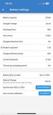
Parallel you add amperage together. Series you add voltage. So you have two 12V batteries in series to create a 125Ah 24V battery. You have three sets of those so it would be 3 x 125Ah, therefore you would enter 375 in the shunt. You should also leave the Peukert exponent at 1.25 since that is for lead acid by default.

sunshine_eggo
Happy Breffast!
Per @ rhino, set peukert to 1.25.
Set battery SoC on reset to "Keep SoC"
Charged voltage should be set to 0.2-0.3V below float for AC charging or 0.2-0.3V below absorption for solar. Unpredictable solar can trigger false sync if set for AC charging.
Set battery SoC on reset to "Keep SoC"
Charged voltage should be set to 0.2-0.3V below float for AC charging or 0.2-0.3V below absorption for solar. Unpredictable solar can trigger false sync if set for AC charging.
Ok how and where do I change that charged voltage setting and to what? ThanksPer @ rhino, set peukert to 1.25.
Set battery SoC on reset to "Keep SoC"
Charged voltage should be set to 0.2-0.3V below float for AC charging or 0.2-0.3V below absorption for solar. Unpredictable solar can trigger false sync if set for AC charging.
sunshine_eggo
Happy Breffast!
Ok how and where do I change that charged voltage setting and to what? Thanks
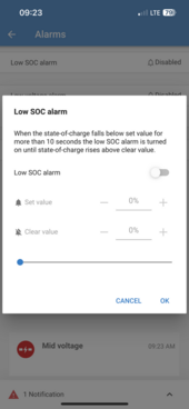
On this screen you linked:

The charged value depends on how your chargers are configured.
Actually, I will respectfully disagree slightly on that charged voltage setting. Always set it to that 0.2-0.3V below ABSORB setpoint. The reason being that if you don't then it can potentially calibrate to 100% prematurely. Normally you should be using the same or very similar absorb charge volts for solar and/or inverter charging. Of course in an all in one unit that will be one and the same setting.
Also just a note for anyone with a 12V battery setup. You still want to go 0.1-0.2V below Absorb voltage. (And on 48V go more like 0.3-0.4V below Absorb.)
Also just a note for anyone with a 12V battery setup. You still want to go 0.1-0.2V below Absorb voltage. (And on 48V go more like 0.3-0.4V below Absorb.)
sunshine_eggo
Happy Breffast!
The shunt is a monitoring device. I does not control anything.
You need to set the absorption voltage in the chargers. What are your chargers?
You need to set the absorption voltage in the chargers. What are your chargers?
What @sunshine_eggo said! You will see and adjust that in your chargers, inverters, solar controllers. Whatever is doing the charging.Where do you see the absorb rate on the pics from the app?
The Smartshunt is only monitoring, hence the need for that small buffer, where the Smartshunt is watching for a voltage slightly below where the voltage will actually go to.
Similar threads
- Replies
- 4
- Views
- 462
- Replies
- 6
- Views
- 381